
Fabric treating apparatus

a technology of fabric and treating apparatus, which is applied in the direction of lighting and heating apparatus, drying machines, cleaning using liquids, etc., can solve the problems of low efficiency of fabric drying and treating apparatus, low space efficiency of treating chamber, and unnecessary space for indoor installation of apparatus, etc., and achieve the effect of improving the space efficiency of the treating chamber

Active Publication Date: 2012-10-30
LG ELECTRONICS INC
View PDF23 Cites 24 Cited by
  • Summary
  • Abstract
  • Description
  • Claims
  • Application Information

AI Technical Summary

Benefits of technology

[0009]An object of the present invention is to provide a fabric treating apparatus and method for improving space efficiency of a treating chamber by disposing a driving unit to the upper part of the outside of a treating chamber
[0010]An object of the present invention is to provide a fabric treating apparatus and method for minimizing the install space by reducing the width of the apparatus.
[0011]An object of the present invention is to provide a fabric treating apparatus and method for improving the dry efficiency by including a fan to circulate the air in the treating chamber.
[0013]An object of the present invention is to provide a fabric treating apparatus and method for making uniform air flow inside of the treating chamber by circulating air in the treating chamber.

Problems solved by technology

The conventional fabric apparatus has problems that the space efficiency of the treating chamber is low because the hanger rack is disposed to be moved inside of the treating room and the driving unit for moving the hanger rack is disposed inside or side of the treating chamber.
Particularly, a fabric treating apparatus which the driving unit is disposed side of the treating chamber has a problem that unnecessary space is needed to install the apparatus indoor because the width of the apparatus is larger.
The conventional fabric treating apparatus has a problem that the efficiency for drying fabrics and the treating apparatus is low because the hot wind and the steam may not flow uniformly in the treating chamber.
Particularly, as the humid air in the treating chamber is condensed and left on the inner wall of the treating chamber, the apparatus has bad smell and is unsanitary.
It has a problem that the fabrics are wet again because the condensed water on inner wall of the treating chamber drops to the fabrics which is finished drying.

Method used


Image

  • Fabric treating apparatus
  • Fabric treating apparatus
  • Fabric treating apparatus

Examples


Embodiment Construction

[0034]The above and other advantages of the present invention will become more apparent by describing in detail embodiments thereof with reference to the attached drawings in which.

[0035]The present invention is not restricted by the following embodiments. It will be understood by those of ordinary skill in the art that various changes in form and details may be made therein without departing from the spirit and scope of the present invention as defined by the following claims.

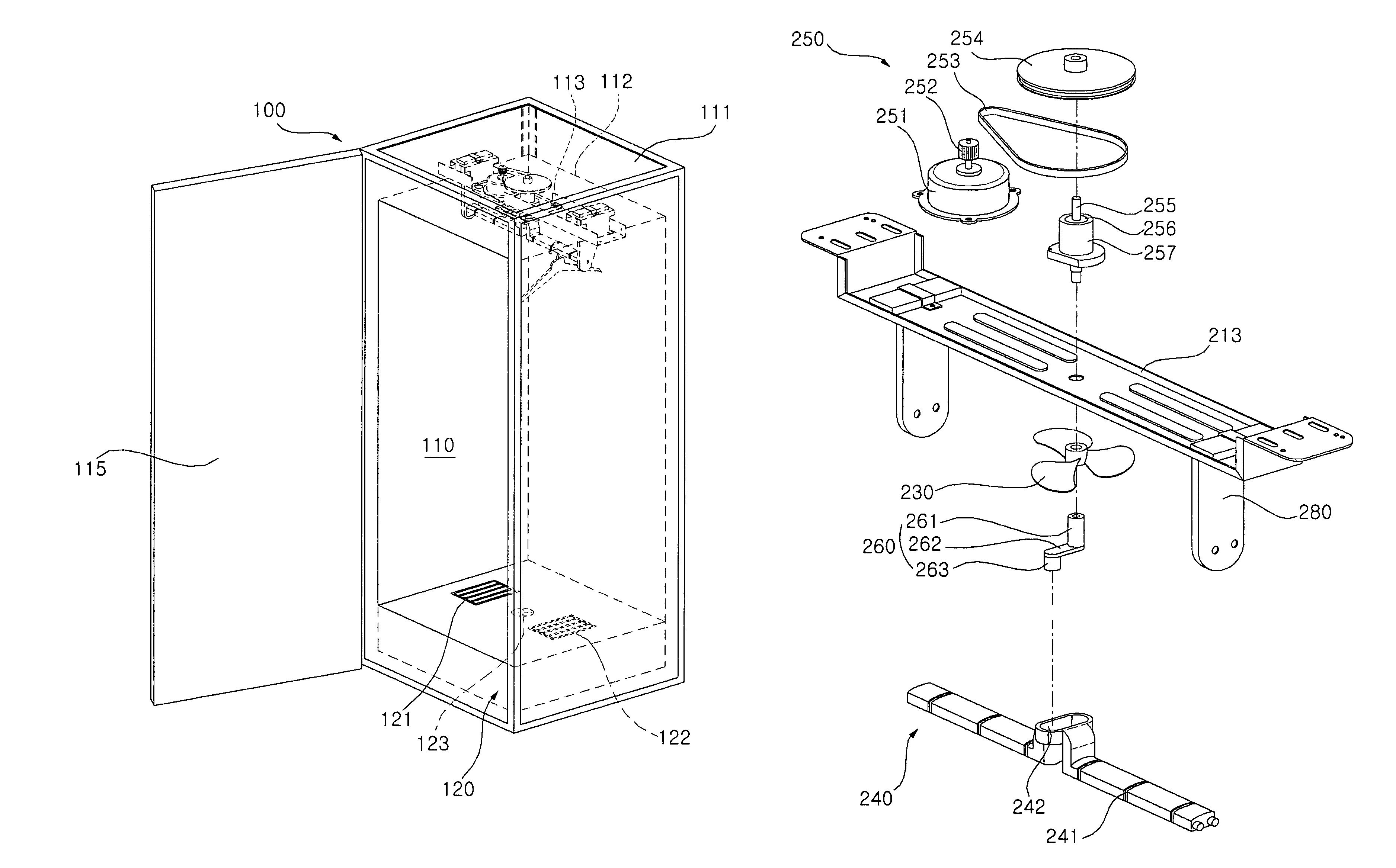
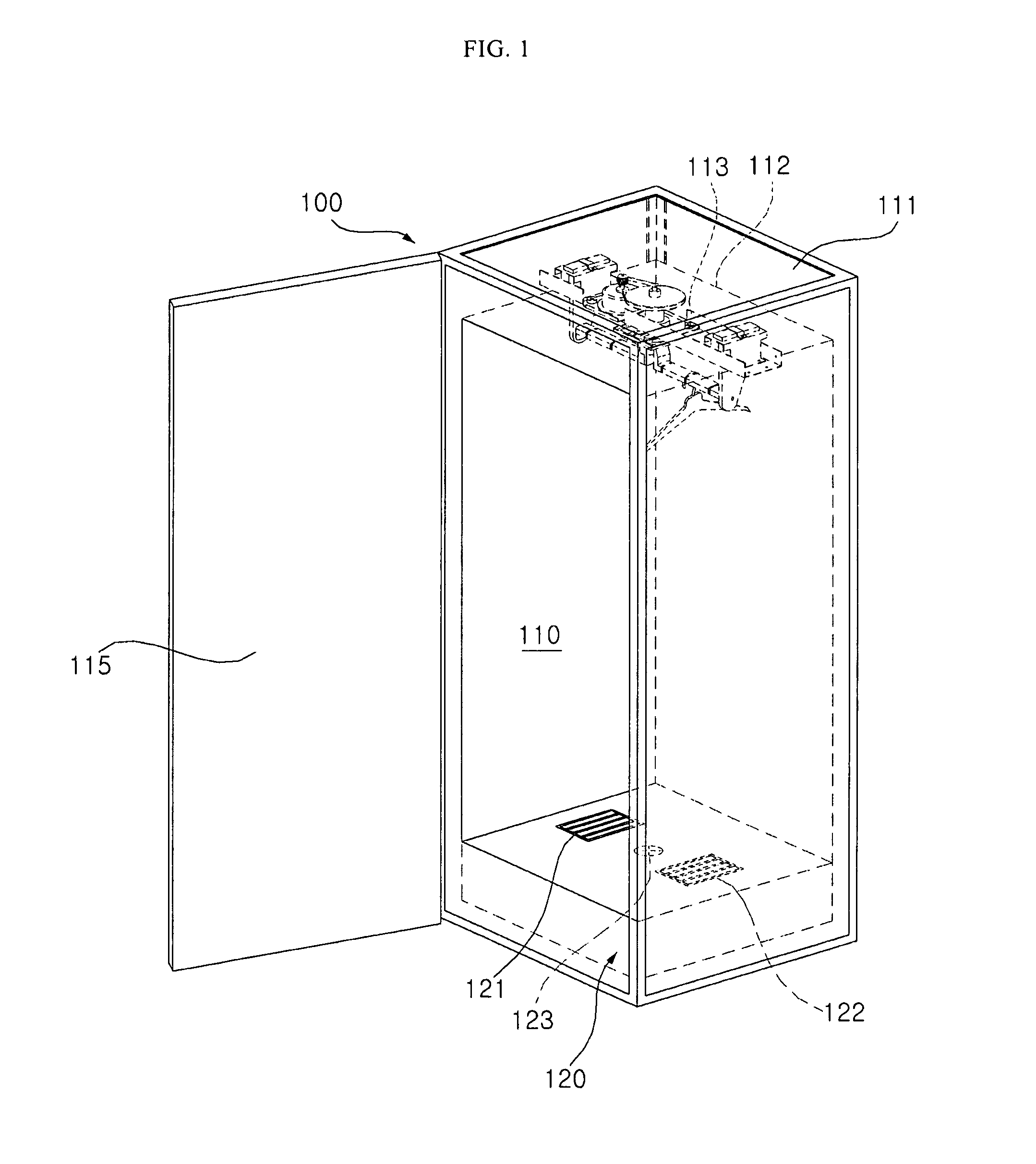
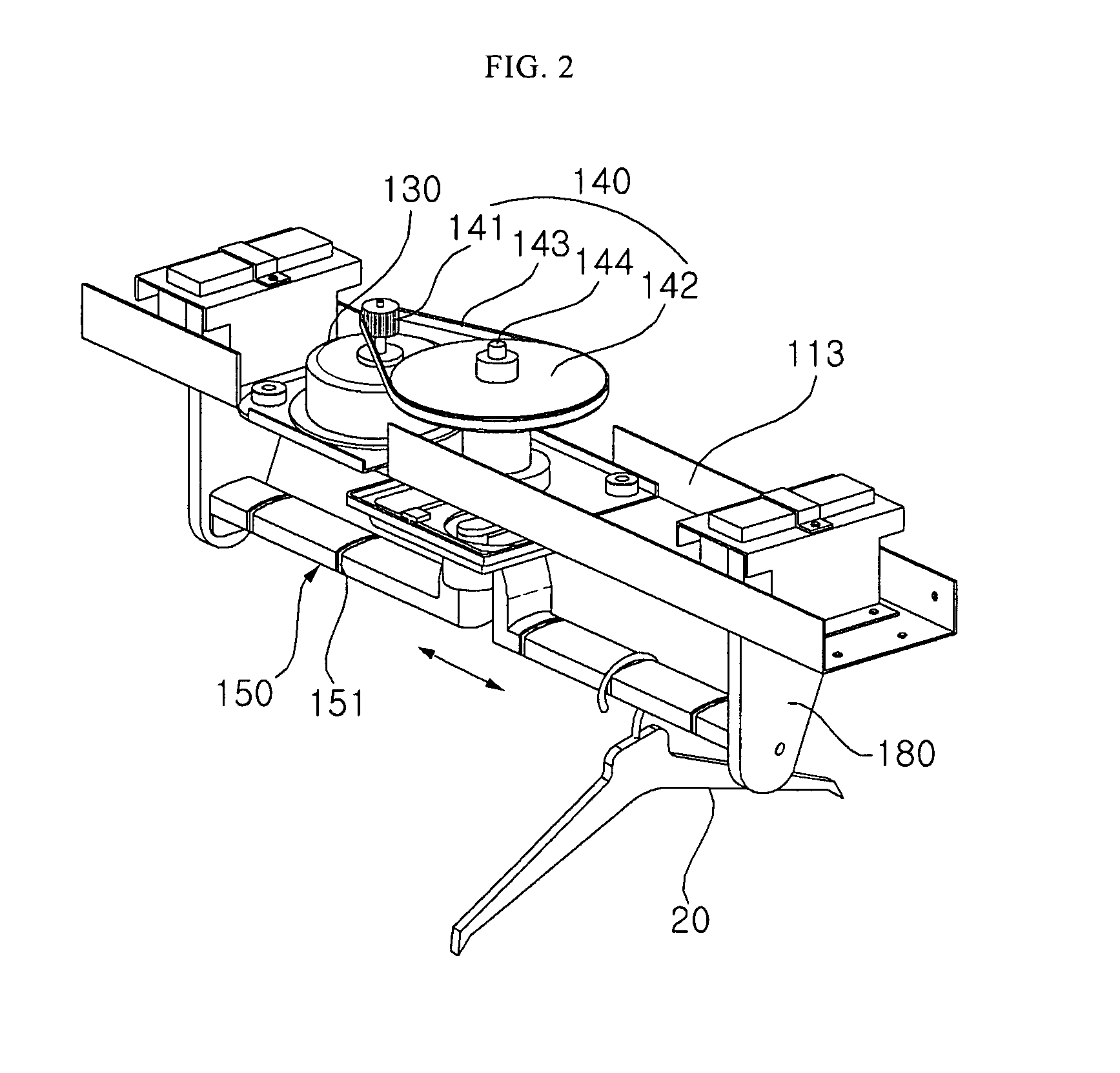
[0036]FIG. 1 illustrates a perspective view of a fabric treating apparatus 100 in accordance with an exemplary embodiment of the present invention. FIG. 2 illustrates a partial enlarged perspective view of main part of main part of a fabric treating apparatus 100 shown in FIG. 1. FIG. 3 illustrates a disassembled perspective view of FIG. 2. FIG. 4 illustrates a perspective view of a power transformation unit shown in FIG. 3.

[0037]A fabric treating apparatus 100 includes an outside cabinet 111 which forms the e...


PUM


Abstract

A present invention relates to a fabric treating apparatus including an inside cabinet which forms a treating chamber which the fabrics treated in, and a heating unit for supplying any one between hot wind and steam to the treating chamber, and a hanger rack disposed in the treating chamber, and a driving unit for generating rotary power outside the treating chamber and is disposed upper part of the inside cabinet, and a transmission unit for reciprocating the hanger rack by transmitting the rotary power of the driving unit.

Description

CROSS-REFERENCE TO RELATED APPLICATIONS[0001]This application claims priority from Korean Patent Application No. 10-2008-0124854 filed on Dec. 9, 2008, and Korean Patent Application No. 10-2008-0124855 filed on Dec. 9, 2008 in the Korean Intellectual Property Office, the disclosure of which is incorporated herein by reference in its entirety.BACKGROUND OF THE INVENTION[0002]1. Field of the Invention[0003]The present invention relates to fabric treating apparatus including a driving unit is disposed upper part of the outside of a treating chamber.[0004]2. Background of the Invention[0005]A fabric treating apparatus includes all devices for treating fabrics by various methods. The methods include functions of drying fabrics using hot wind. The methods include functions of removing the wrinkles from the fabrics or sterilizing the fabrics or removing a bad smell from the fabrics or supplying aroma to the fabrics or preventing generation of static electricity using a steam and the hot wi...

Claims


Application Information

Patent Timeline
Patent Type & Authority Patents(United States)
IPC IPC(8): F26B11/00
CPCD06F58/12D06F58/20F26B11/12
Inventor KIM, SUNG MINHONG, SOG KIEKIM, DONG WONKIM, JONG SEOKPARK, DAE YUNYOO, HEA KYUNG
Owner LG ELECTRONICS INC
Learn More