
Method of manufacturing a fixture of a dental implant

a technology of dental implants and fixtures, which is applied in the field of dental implants fixing, can solve the problems of affecting the success of osseointegration, affecting the osseointegration success, and affecting the structure of the fixture, so as to improve the structure, improve the osseointegration performance, and reduce the spread of inflammation

Inactive Publication Date: 2012-10-30
HYUN
View PDF10 Cites 1 Cited by
  • Summary
  • Abstract
  • Description
  • Claims
  • Application Information

AI Technical Summary

Benefits of technology

[0014]The present invention provides a method of manufacturing a fixture of a dental implant with an improved structure in which the performance of osseointegration is excellent, spread of inflammation is reduced and a combination force between the fixture and an alveolar bone is remarkably increased, and a fixture of a dental implant manufactured by the method.
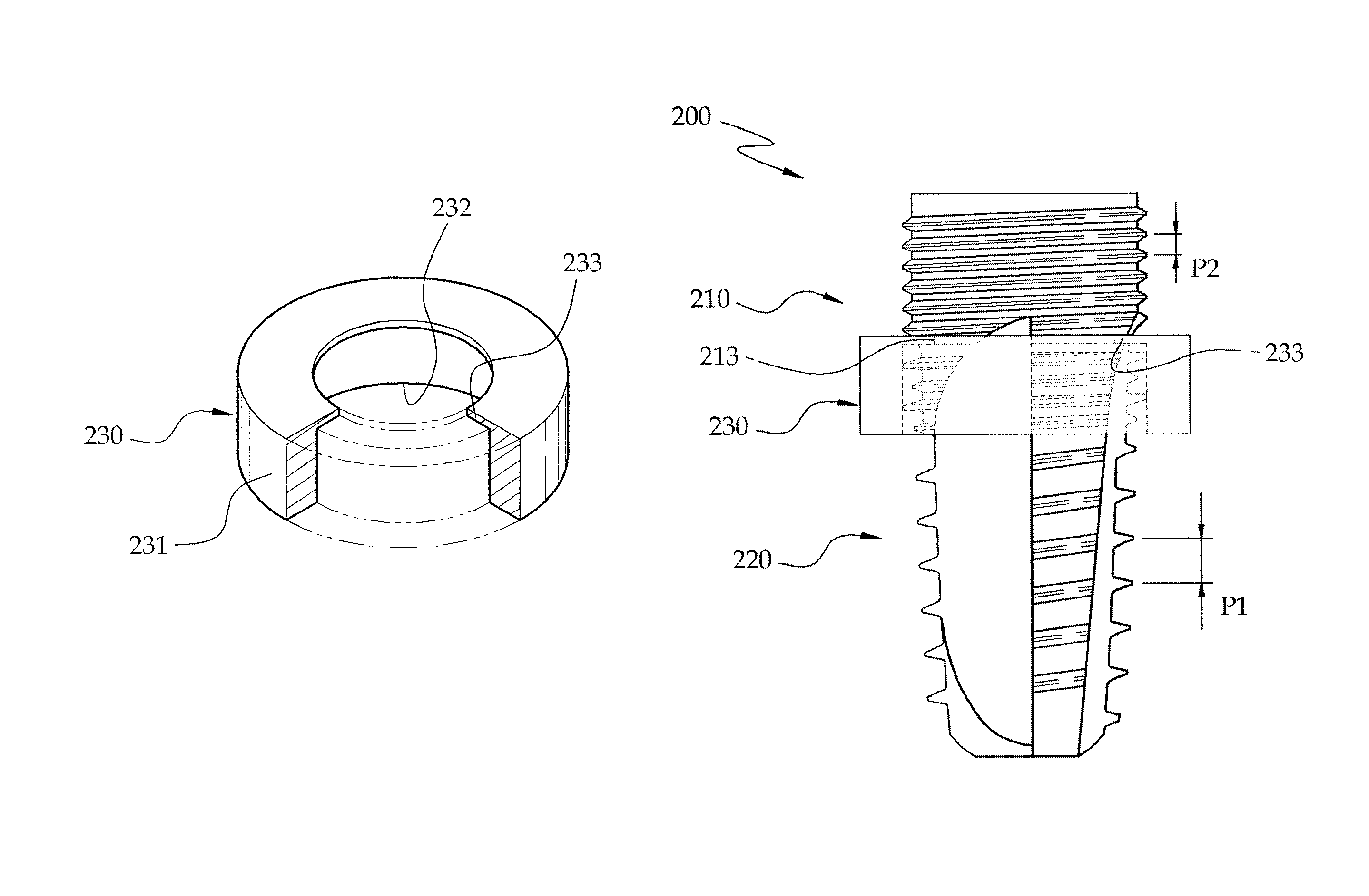
[0015]According to an aspect of the present invention, there is provided a method of manufacturing a fixture of a dental implant, the method including: cutting including forming a male screw portion of the fixture; fixing a ring-shaped protection jig by inserting the protection jig in the male screw portion of the fixture to surround portions of the male screw portion in a circumferential direction; performing surface processing on the male screw portion of the fixture to improve a surface roughness of the male screw portion; and removing the protection jig fixed on the male screw portion from the male screw portion of the fixture.

Problems solved by technology

When osseointegration is not successfully done, bone resorption or progressive bone loss occurs.
It is widely known that a surface roughness of the fixture affects the success of osseointegration.
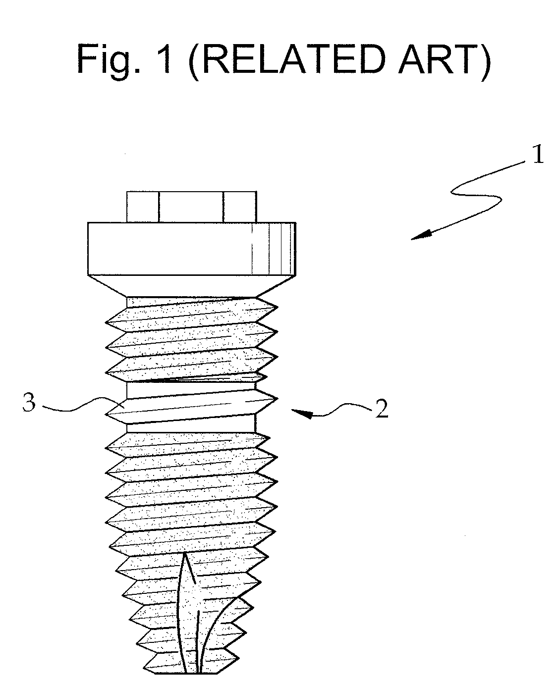
However, the rough surface of the fixture promotes progress of infection when inflammation occurs around the implant.
In other words, it is reported that, when the surface of the fixture is more rough than a polished surface, infection progresses more quickly along the surface of the fixture.

Method used


Image

  • Method of manufacturing a fixture of a dental implant
  • Method of manufacturing a fixture of a dental implant
  • Method of manufacturing a fixture of a dental implant

Examples


Embodiment Construction

[0022]The present invention will now be described more fully with reference to the accompanying drawings, in which exemplary embodiments of the invention are shown.

[0023]FIGS. 2 through 5 illustrate a method of manufacturing a fixture 100 of a dental implant, according to an embodiment of the present invention.

[0024]Referring to FIG. 2, the method of manufacturing the fixture 100 of the dental implant according to the current embodiment of the present invention includes cutting a screw portion including forming a lower screw portion 120 and an upper screw portion 110 by cutting the fixture 100 of the dental implant. Cutting of the screw portion is performed by two operations, i.e., forming of the lower screw portion 120 and forming of the upper screw portion 110. In the forming of the lower screw portion 120, the lower screw portion 120 is formed by cutting a screw having one thread at a lower side of the fixture 100. In the forming of the upper screw portion 110, the upper screw po...


PUM

PropertyMeasurementUnit
widthaaaaaaaaaa
widthaaaaaaaaaa
depthaaaaaaaaaa

Abstract

Provided are a method of manufacturing a fixture of a dental implant with an improved structure in which the performance of osseointegration is excellent, spread of inflammation is reduced and a combination force between the fixture and an alveolar bone is remarkably increased, and a fixture of a dental implant manufactured by the method. The performance of osseointegration is excellent, and spread of inflammation can be reduced, and a combination between the fixture and an alveolar bone can be remarkably improved. Furthermore, the fixture of the dental implant having the above structure can be easily manufactured.

Description

CROSS-REFERENCE TO RELATED PATENT APPLICATION[0001]This application claims the benefit of Korean Patent Application No. 10-2009-0057048, filed on Jun. 25, 2009 and Korean Utility Model Application No. 20-2009-0008318 filed on Jun. 29, 2009, in the Korean Intellectual Property Office, the disclosure of which is incorporated herein in its entirety by reference.BACKGROUND OF THE INVENTION[0002]1. Field of the Invention[0003]The present invention relates to a fixture of a dental implant and a method of manufacturing the same, and more particularly, to a fixture of a dental implant that allows fast bone formation at an early stage and prevents infection and inflammation, and a method of easily manufacturing the fixture.[0004]2. Description of the Related Art[0005]Generally, dental implants include a fixture, an abutment, and a crown.[0006]A male screw portion is formed in the fixture, is inserted in an alveolar bone of a human body and supports and fixes a dental implant.[0007]The abutme...

Claims


Application Information

Patent Timeline
Patent Type & Authority Patents(United States)
IPC IPC(8): A61C5/09A61C8/00A61C5/73
CPCA61C8/0012A61C8/0025A61C8/005A61C8/0016Y10T29/49567A61C8/0024
Inventor HYUN, YOUNG KEUN
Owner HYUN
Learn More