Method and system for processing data

a data processing and data technology, applied in the field of real-time data transmission methods and systems, can solve the problems of only partially balancing out of ethernet switches, relatively large wiring expenditure, and unknown delay time, and achieve the effect of reducing the latency of data transmission

Inactive Publication Date: 2012-10-16
ROBERT BOSCH GMBH
View PDF23 Cites 0 Cited by
  • Summary
  • Abstract
  • Description
  • Claims
  • Application Information

AI Technical Summary

Benefits of technology

[0005]Example embodiments of the present invention provide a method and a system for real time transmission which has minimum latency times in the data transmission.
[0007]One advantage of the method is that the wiring expenditure is minimized compared to the star topology shown in FIG. 1.
[0008]An additional advantage of the method is that the predictability of the data transmission, that is, the jitter of the latency times occurring in response to the data transmission is minimal.
[0011]This has the advantage that the periodicity of the data transmitted by a module is able to be set by a suitable selection of the masking value (frame mask) and the identification number (frame ID).

Problems solved by technology

If several measuring units simultaneously send data in the direction towards the PC, collisions take place which the Ethernet switch is only partially able to balance out.
In the course of that, there comes about an unknown delay time between the creation of the data in the measuring unit MG and the arrival of the data at the PC.
The star-shaped topology shown in FIG. 1 also has the disadvantage that the wiring expenditure is relatively large.
However, the disadvantage of a data transmission after a handshake method is that the bandwidth provided by the Ethernet is not able to be fully utilized, since either data are sent from the PC to a measuring unit MG or conversely data from a measuring unit MG to the PC.
Real time requirements, such as particularly the predictability of the data transmission times and short latency times, are therefore not satisfied in such usual Ethernet systems.

Method used


Image

  • Method and system for processing data
  • Method and system for processing data
  • Method and system for processing data

Examples


Embodiment Construction

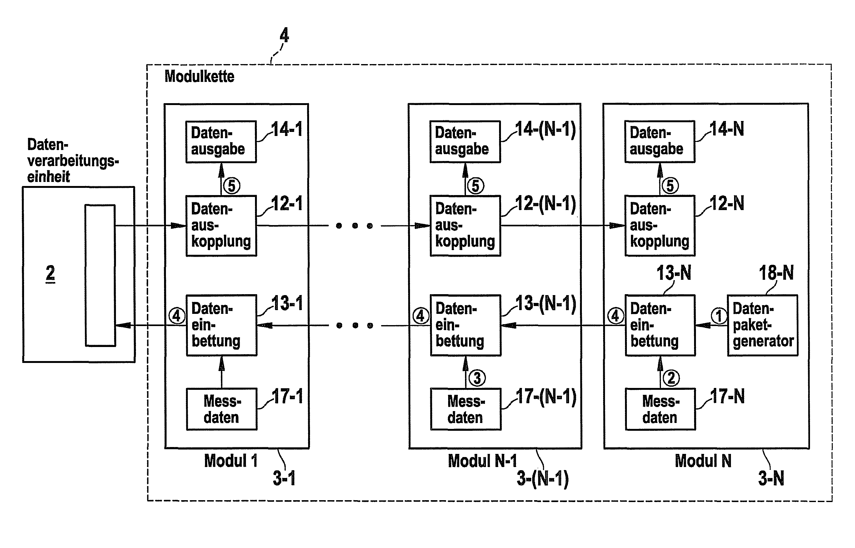
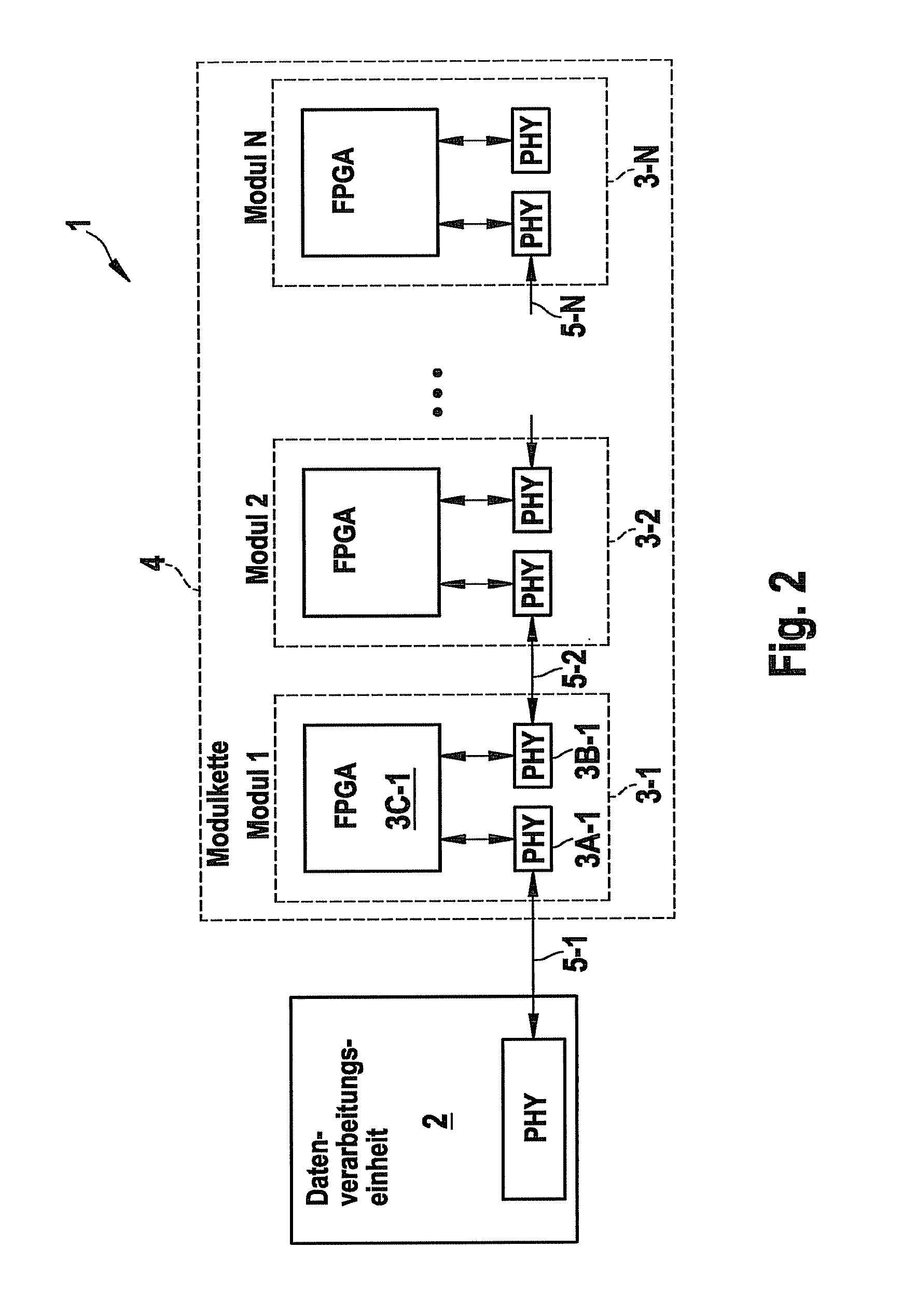
[0050]As may be seen in FIG. 2, a real time data transmission system 1 includes at least one data processing unit 2, to which a module chain 4 made up of modules 3 is able to be connected. Module chain 4 includes N modules 3 that are serially connected to one another. Modules 3 are any module or measuring units which supply real time measured data. Modules 3 are linked to one another via a cable 5, first module 3-1 of module chain 4 being connected via a cable 5-1 to data processing unit 2. The data transmission medium or cable 5-i is any data transmission cable. In an alternative example embodiment, the data transmission between the modules takes place in a wireless manner. In the specific embodiment shown in FIG. 2, each module 3 includes two transceivers PHY for data transmission. Furthermore, each module includes one FPGA unit (FPGA: field programmable gate array).

[0051]Transceivers PHY are preferably transceivers for transmitting Ethernet data packets. One of the two Ethernet t...


PUM


Abstract

In a system and a method for real time transmission between modules that are serially connected to one another, each module embeds its useful data in a data packet received by a preconnected module, which has a data packet number, if a comparison value formed as a function of the data packet number agrees with an identification number (frameID) that is provided in the module.

Description

FIELD OF THE INVENTION[0001]The present invention relates to a method and a system for real time data transmission between modules linked serially to one another, especially between measuring unit modules.BACKGROUND INFORMATION[0002]Field buses or process networks are used for real time data transmission between actuators and sensors, especially in the field of automation technology. The data have to be transmitted via the field bus in ensured fashion within an established time span, so that field buses make a high demand on the latency for data transmission. The Ethernet is also increasingly being used as a field bus, a broad use of data transmission protocols from the TCP / IP protocol family being striven for. The Ethernet standard specifies various data transmission speeds, such as Ethernet networks having data transmission speeds of 10 Mbit per second, 100 Mbit per second and 1 Gbit per second. Moreover, there are Ethernet networks in which the data are transmitted in a wireless ...

Claims


Application Information

Patent Timeline
Patent Type & Authority Patents(United States)
IPC IPC(8): H04L12/28
CPCH04L12/403H04L12/417H04L2012/4026H04L12/28H04L65/40
Inventor FROHNA, MICHAELROETTGER, KAI
Owner ROBERT BOSCH GMBH
Why Eureka
Try Eureka