Intermediate fixing element

a technology of fixing element and loop, which is applied in the field can solve the problems of poor quality of the hook of the intermediate fixing element with the loop, long production cycle of this type of intermediate fixing element, and tendency to become unhooked

Active Publication Date: 2012-10-09
APLIX INC
View PDF12 Cites 9 Cited by
  • Summary
  • Abstract
  • Description
  • Claims
  • Application Information

AI Technical Summary

Benefits of technology

[0006]This invention aims to overcome the drawbacks of the prior art by proposing a fastening element of the type previously described which allows an excellent fastening to be obtained, even in the long term, which does not deteriorate as a result of vibrations and which can still be produced rapidly and cost-effectively.
[0020]By thus providing such forms and dimensions of the hooks, it is easy to produce in a single moulding stage the intermediate fastening element with removal of the hooks from the moulds, in spite of the rigidity of the plate.

Problems solved by technology

The production of this type of intermediate fastening element is long and complex and not well adapted to large-scale industrial production, particularly by reason of the fact that these intermediate fastening elements are not realised from a single element.
In use, the fastening of the hooks of these fastening elements with loops is of poor quality, having a tendency to become unhooked in the long term due to the effect of vibrations, particularly in a motor car, by progressive peeling.

Method used


Image

  • Intermediate fixing element
  • Intermediate fixing element
  • Intermediate fixing element

Examples


Embodiment Construction

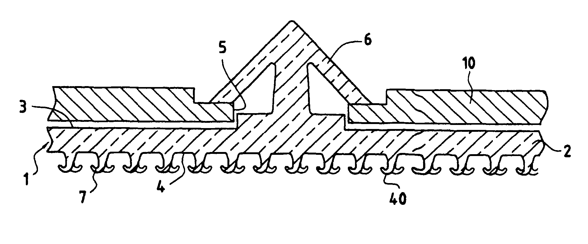
[0034]In FIG. 1, an intermediate fastening element 1 according to the invention is shown. The intermediate fastening element 1 is constituted by a plate 2 which is substantially rigid, that is to say having a form which cannot bend in itself or on account of the effect of its own weight. Besides, the plate cannot be irreversibly bent beyond an angle of curvature of 5°. This angle of curvature is defined in the following way. The plate is placed on a plane, maintaining it on one of its edges, whereas an opposing edge is pulled upwards to bend the plate. The angle of curvature is the angle between the tangent to the part of the plate at the edge which has been pulled and the plane.

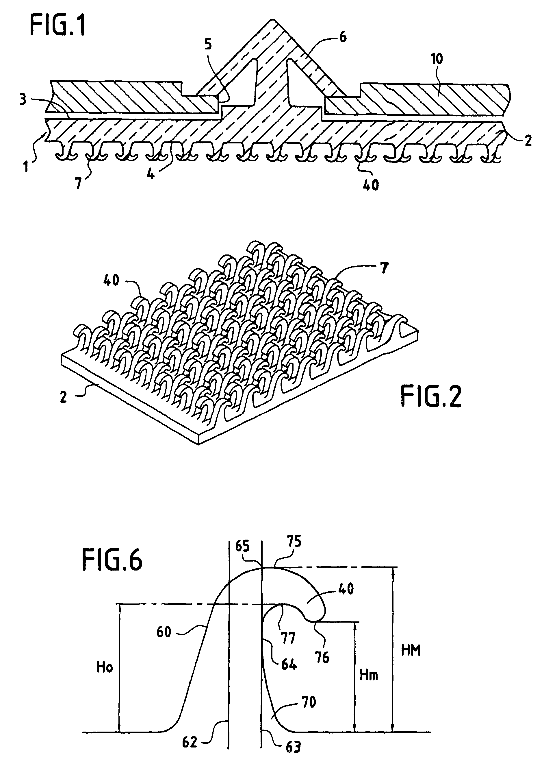
[0035]The plate 2 is in the shape of a square, having an upper face 3 and a lower face 4. Coming from the upper face 3 is an anchoring element 6 in the shape of a fir tree, while hooks 7 come from the lower face 4. Preferably, the hooks 7 cover at least half of the surface area of the lower face 4 upon obser...


PUM

PropertyMeasurementUnit
Thicknessaaaaaaaaaa
Thicknessaaaaaaaaaa
Thicknessaaaaaaaaaa

Abstract

The inventive intermediate fixing element (1) is embodied in one piece by injection moulding and comprises a plate (2) which is substentially flat and comprises a first or top surface and a second or lower surface, at least one anchoring element (6), for example in the form of a herringbone or a tree produced directly by the top surface moulding and hooks (7) which are produced directly by the lower surface moulding and whose shape, sizes and thermoplastic material are selected in such a way that said hooks, after being shaped in a mould and extracted therefrom, substentially recover the initial shape thereof, wherein said hooks are sufficiently flexible in order to be bent during extraction from the mould.

Description

TECHNICAL FIELD[0001]This invention relates to an intermediate fastening element which is intended to provide the connection between a first element and a second element, and comprising a plate from which on the one hand hooks project for fastening through cooperation with loops of the second element and on the other hand an anchoring element, particularly in the shape of a fir tree, for fastening to the first element. This invention also relates to an assembly constituted by a first element, a second element and an intermediate fastening element according to the invention.BACKGROUND ART[0002]For example, in the field of the motor car, there is often a need to fasten to a first element, for example to a roof, a second element, for example a vehicle roof element. It is desirable, for example in the case of repair, to be able to remove the vehicle roof element.[0003]In order to do this, an intermediate fastening element is known which is constituted by a flat plate having a first surf...

Claims


Application Information

Patent Timeline
IPC IPC(8): A44B18/00F16B5/07
CPCA44B18/0061F16B5/07Y10T24/2725Y10T24/2792A44B18/00
Inventor HAMMER, PAVELHAMMER, LEGAL REPRESENTATIVE, MARION
Owner APLIX INC
Why Eureka
Try Eureka