
Mobility mechanisms for home cellular network

a mobile mechanism and home cellular network technology, applied in the field of wireless networking, can solve the problems of presenting a new problem, wasting significant processing ability, and unable to maintain a satisfactory communication link

Active Publication Date: 2012-10-02
IND TECH RES INST
View PDF10 Cites 21 Cited by
  • Summary
  • Abstract
  • Description
  • Claims
  • Application Information

AI Technical Summary

Benefits of technology

[0013]As the number of handovers each base station must execute increases, the processing costs of the handover could overwhelm and eventually shut down a communications network. Thus, a need exists to increase the efficiency of a handover when a large number of additional base stations, such as femtocell networks, are implemented within a communication network.

Problems solved by technology

A conventional problem in the art has been maintaining a communication link quality of sufficient strength to enable communication between a mobile client device and a base station in a wireless network.
Practically, however, there are many challenges to maintaining a satisfactory communication link.
Geographical terrain, natural obstacles, and man made obstacles all affect the link quality of the communication link between a base station and a mobile client device.
Unfortunately, when a mobile client device attempts to access the service signal from a closed access femtocell network to which it was not previously registered, significant processing ability is wasted by the femtocell network to recognize the mobile client is not registered and deny it a service connection.
This solution, however, presents a new problem.
Drawbacks to these conventional handovers include significant processing costs, communication delays, and communication interruptions.
As the number of handovers each base station must execute increases, the processing costs of the handover could overwhelm and eventually shut down a communications network.

Method used

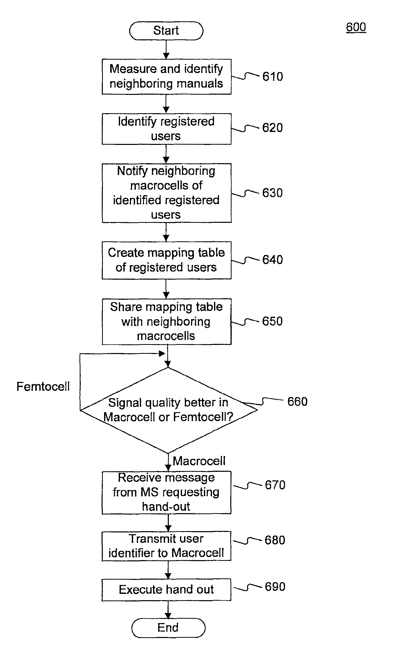
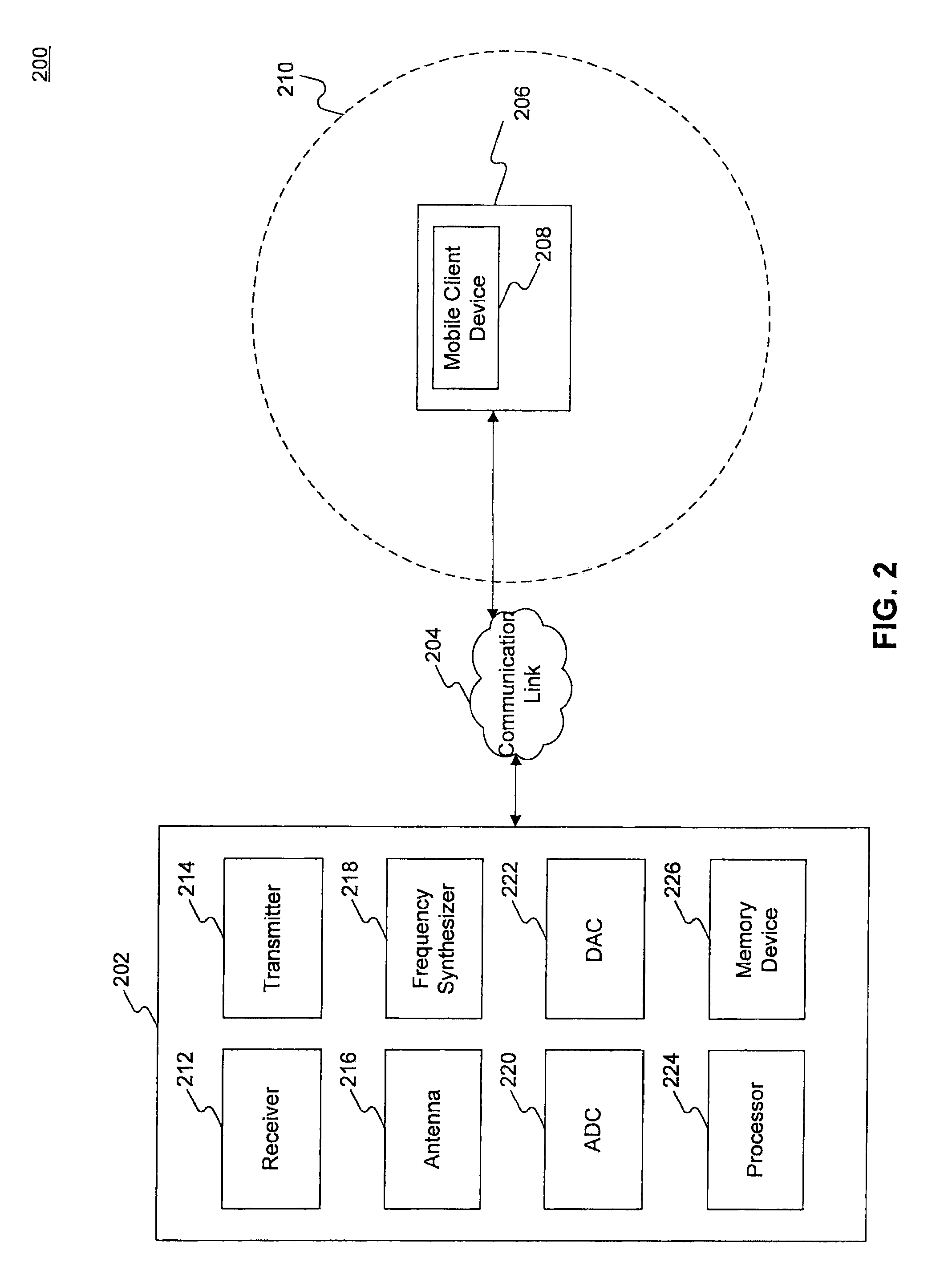

Image

  • Mobility mechanisms for home cellular network
  • Mobility mechanisms for home cellular network
  • Mobility mechanisms for home cellular network

Examples


Embodiment Construction

[0025]In the following description, for purposes of explanation and not limitation, specific techniques and embodiments are set forth, such as particular sequences of steps, interfaces and configurations, in order to provide a thorough understanding of the techniques presented herein. While the techniques and embodiments will primarily be described in context with the accompanying drawings, those skilled in the art will further appreciate that the techniques and embodiments may also be practiced in other network types.

[0026]Reference will now be made in detail to the exemplary embodiments, examples of which are illustrated in the accompanying drawings. Wherever possible, the same reference numbers are used throughout the drawings to refer to the same or like parts.

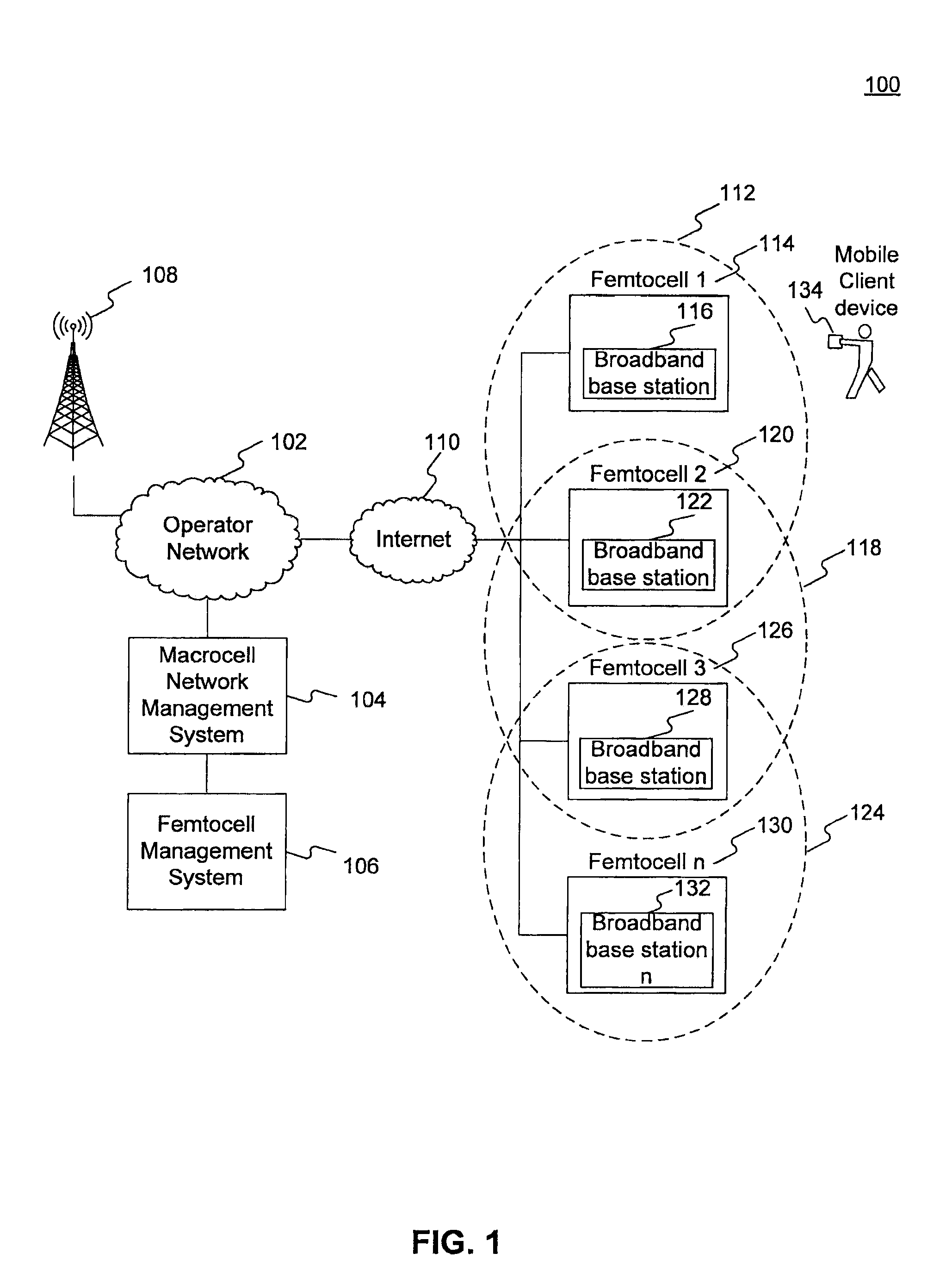
[0027]FIG. 1 is a block diagram illustrating a wireless communication system 100 in accordance with an exemplary embodiment. Communication system 100 facilitates communication between various electronic devices by way of o...


PUM


Abstract

A communication system comprises a communication network including a computer processor operating a network management system and a femtocell network management system. The communication system further comprises a broadband base station providing a first service signal and creating a mapping table configured to include at least one unique identifier of a mobile client device and a base station providing a second service signal and receiving the mapping table from the broadband base station. A computer processor in the communication system is configured to determine a link quality of a mobile client device service signal received by the broadband base station, the contents of the mapping table, and the unique identifier of the mobile client device to determine whether the broadband base station will provide the first service signal to the mobile client device or whether the base station will provide the second service signal to the mobile client device.

Description

PRIOR APPLICATION[0001]This application claims the benefit of priority to U.S. Provisional Patent Application No. 61 / 110,031, filed Oct. 31, 2008, entitled “MOBILITY MECHANISMS FOR HOME CELLULAR NETWORK,” the entire contents of which are hereby incorporated by reference in its entirety.BRIEF DESCRIPTION[0002]1. Technical Field[0003]A system and method disclosed herein generally relate to wireless networking and, more specifically, to a system and method that increases wireless connectivity in an indoor network area.[0004]2. Description of the Related Art[0005]A conventional wireless network environment connects mobile electronic devices to a service provider. A wireless network environment is often configured to create a mobile communication system that may provide wireless service to mobile client devices. A mobile communication system often includes at least one base station and at least one client device, which is typically each configured to transmit and receive information to a...

Claims


Application Information

Patent Timeline
Patent Type & Authority Patents(United States)
IPC IPC(8): H04W4/00
CPCH04W36/30H04W36/04H04W84/045
Inventor CHOU, CHIE-MINGREN, FANG-CHING
Owner IND TECH RES INST
Learn More