Display device
a display device and display angle technology, applied in the field of display devices, can solve the problems of degrading the fineness of an image in the window, complicating the structure of the display device, and difficult to control the orientation and viewing angle as well, so as to achieve simple structure and control the viewing angle, and achieve the effect of not degrading the fineness of images
- Summary
- Abstract
- Description
- Claims
- Application Information
AI Technical Summary
Benefits of technology
Problems solved by technology
Method used
Image
Examples
first embodiment
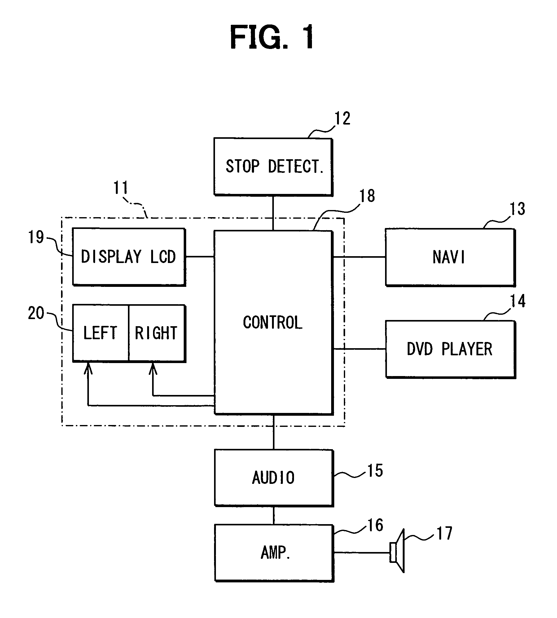
[0028]A display device 11 according to a first embodiment of the present invention will be explained with reference to FIGS. 1 to 5.
[0029]Structure of In-Vehicle System
[0030]With referring to FIG. 1, a display device 11 provided in a subject vehicle includes a stop state detector 12, imaging devices such as a navigation device 13 and a DVD player 14, an audio device 15, an amplifier 16, and a speaker 17. The display device 11 may further include another imaging device such as a TV tuner other than the navigation device 13 and DVD player 14.
[0031]The stop state detector 12 detects whether the vehicle is in a stop state, i.e., whether the vehicle stops or runs. This stop state detector 12 can be a speed sensor to detect a vehicle speed or a sensor to detect a state of an emergency brake.
[0032]The navigation device 13 includes a map database, a GPS receiver, and an autonomous navigation sensor, to detect a position of the vehicle and to output image signals and audio signals. The image...
second embodiment
[0065]A display device 11 according to a second embodiment will be explained with reference to FIGS. 6, 7A, 7B, 8, and 9. A structure of the display device 11 and in-vehicle system including the device 11 is the same as that of the first embodiment. The same part as the first embodiment is omitted from explanation.
[0066]The second embodiment is different from the first embodiment in the display control. An outline of the display control will be explained with reference to FIG. 6. When the vehicle stops, an identical image or window can be visible from both the driver seat and front passenger seat. The window is displayed in the full-screen size. In contrast, when the vehicle runs, two different full-screen windows are displayed for the driver seat and front passenger seat; namely, a full-screen window (i.e., a map window) visible from the driver is different from a full-screen window (i.e., a maintenance window) visible from the front passenger seat.
[0067]Details of the display cont...
third embodiment
[0073]Structure of In-Vehicle System
[0074]With referring to FIG. 10, a display device 111 provided in a subject vehicle includes imaging devices such as a navigation device 13 and a DVD player 14, an audio device 15, an amplifier 16, and a speaker 17. The display device 11 may further include another imaging device such as a TV tuner other than the navigation device 13 and DVD player 14.
[0075]The navigation device 13 includes a map database, a GPS receiver, and an autonomous navigation sensor, to detect a position of the vehicle and to output image signals and audio signals. The image signals include map images to show a position of the vehicle, a surrounding area, an enlarged intersection with a heading direction of the vehicle, or the like. The audio signals include an audio guidance.
[0076]The display device 11 includes a display controller 18, a liquid crystal display (LCD) 19 for display (i.e., a display LCD 19), and a light-shielding layer 120 to control a viewing angle. The li...
PUM
 Abstract
Description
Claims
Application Information
 - R&D
- Intellectual Property
- Life Sciences
- Materials
- Tech Scout
- Unparalleled Data Quality
- Higher Quality Content
- 60% Fewer Hallucinations
Browse by: Latest US Patents, China's latest patents, Technical Efficacy Thesaurus, Application Domain, Technology Topic, Popular Technical Reports.
© 2025 PatSnap. All rights reserved.Legal|Privacy policy|Modern Slavery Act Transparency Statement|Sitemap|About US| Contact US: help@patsnap.com


