
Resin injection mold

a resin injection mold and injection molding technology, applied in the field of resin injection molds, can solve the problems of insufficient heating ability and cooling ability of the mold surface, takes time to cool the mold, etc., and achieve the effects of preventing non-infilling of resin, and faster heating and cooling of the resin injection mold surfa

Active Publication Date: 2012-09-25
PANASONIC CORP
View PDF18 Cites 4 Cited by
  • Summary
  • Abstract
  • Description
  • Claims
  • Application Information

AI Technical Summary

Benefits of technology

"The present invention provides a resin injection mold that can quickly heat and cool. This is achieved by including a shaped part produced by metal stereolithography, which has a low-density shaping part and a vent for blowing warm air and cold air. The low-density shaping part is in contact with a resin molding part, which allows for faster heating and cooling of the mold surface. The entire surface in contact with the resin molding part is the low-density shaping part, which increases the amount of air to be sent and allows for faster temperature adjustment and gas sucking. Additionally, the outer periphery of the shaped part includes a high-density shaped part having no air permeability, which enhances the strength of the resin injection mold."

Problems solved by technology

In order to do so, however, if the mold surface is heated using warm water or a heater, the entire mold is heated, and if a volume of the mold is large, it takes time to rise the temperature of the mold surface to a temperature required for molding the resin, and it also takes time to cool the mold.
In such a mold, however, heating ability and cooling ability of the mold surface are insufficient.

Method used


Image

  • Resin injection mold
  • Resin injection mold
  • Resin injection mold

Examples


first embodiment

(First Embodiment)

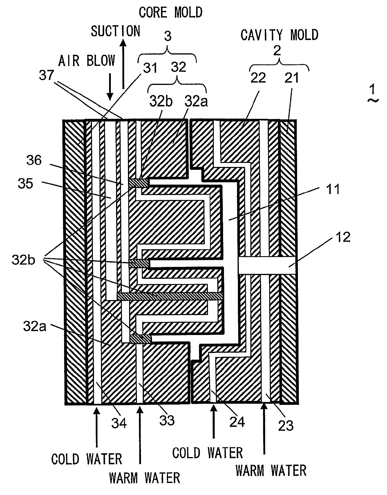
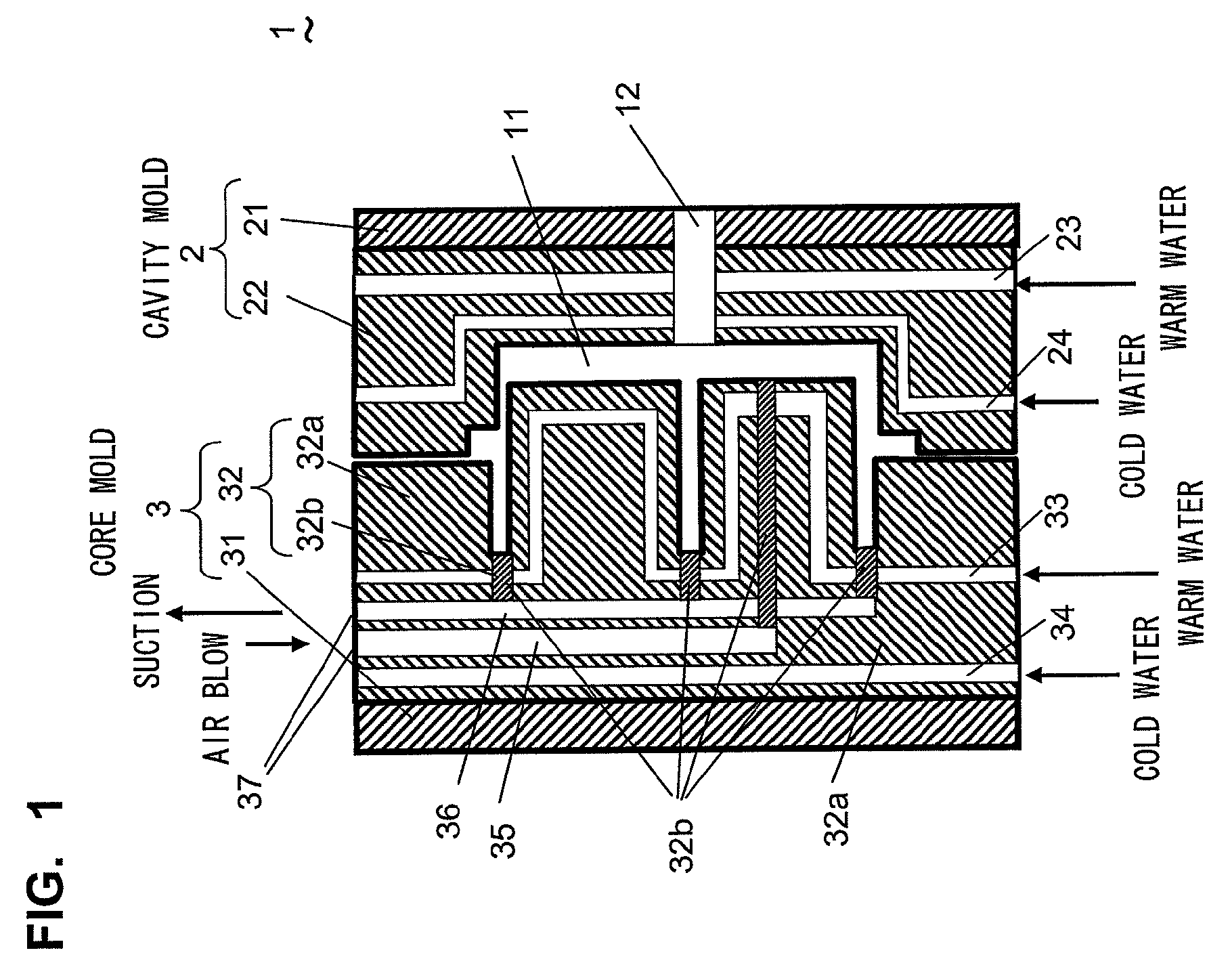
[0021]A resin injection mold (mold, hereinafter) according to a first embodiment of the present invention will be described with reference to FIG. 1. FIG. 1 shows a configuration of the mold 1. The mold 1 includes a cavity mold 2 and a core mold 3, and a resin molding part 11 which molds a resin is formed between the cavity mold 2 and the core mold 3. The cavity mold 2 and the core mold 3 are formed by sintering metal powder on base plates 21 and 31 by later-described metal stereolithography, and forming shaped parts 22 and 32. The shaped part 32 of the core mold 3 is formed from a high-density shaped part 32a except a portion of the shaped part 32, and the portion is formed from a low-density shaping part 32b. A sintered density of the metal powder of the high-density shaped part 32a is 95% or higher. A sintered density of the metal powder of the low-density shaping part 32b is 70 to 95%, and holes are in communication with each other.

[0022]The cavity mold 2 inclu...

second embodiment

(Second Embodiment)

[0040]A resin injection mold according to a second embodiment of the invention will be described with reference to FIG. 7. FIG. 7 shows a sectional view of a core mold 3. The core mold 3 is opposed to a cavity mold (not shown, but this is the same as that described in the first embodiment, and the same is applied in the subsequent embodiments also), and a resin molding part is formed between the core mold 3 and the cavity mold. The core mold 3 is formed from the high-density shaped part 32a except a portion of a shaped part 32, and an air blowing passage 35 formed from a low-density shaping part 32b is formed in a high-density shaped part 32a. The air blowing passage 35 passes through only the interior of the core mold 3. Since warm air and cold air can be blown to the low-density shaping part 32b, the core mold 3 can be heated or cooled faster.

third embodiment

(Third Embodiment)

[0041]A resin injection mold according to a third embodiment of the invention will be described with reference to FIG. 8. FIG. 8 shows a sectional view of a core mold 3. All of surfaces which contact the resin molding part 11 of the core mold 3 are formed from a low-density shaping part 32b and only an outer periphery of the core mold 3 which is not in contact with a resin molding part is formed from a high-density shaped part 32a. An air blowing passage 35 which is in communication with the low-density shaping part 32b is provided in a base plate 31 of the core mold 3. Since an area of the low-density shaping part 32b of the core mold 3 which is in contact with the resin molding part is wide, it is possible to swiftly adjust a temperature of surfaces of the core mold 3 and the cavity mold when warm air or cold air is sent from the air blowing passage 35 to the resin molding part through the low-density shaping part 32b. When gas is sucked from the air blowing pass...


PUM

PropertyMeasurementUnit
temperatureaaaaaaaaaa
densityaaaaaaaaaa
air permeabilityaaaaaaaaaa

Abstract

Disclosed is a mold for resin injection molding that can realize rapid heating or cooling. A resin injection molding mold includes a cavity mold and a core mold and is produced on a base plate by metal photofabrication. The cavity mold is provided with a cavity warm water circuit for allowing warm water for heating to flow and a cavity cold water circuit for allowing cold water for cooling to flow. The core mold is also provided with a core warm water circuit and a core cold water circuit. The core mold includes an air blowing passage for feeding warm air or cold air into a resin molding part and a suction passage (36) for sucking a gas within the resin molding part. The resin molding part side of the air blowing passage and the suction passage is formed of a low-density shaping part that has a low metallic powder sintered density and is permeable to gas. Warm air or cold air can be blown through the low-density shaping part, whereby rapid heating or cooling of the resin injection molding mold can be realized.

Description

TECHNICAL FIELD[0001]The present invention relates to a resin injection mold produced by metal stereolithography.BACKGROUND TECHNIQUE[0002]Conventionally, a mold used for injection molding a resin is known. A temperature of the resin injection mold is adjusted by flowing water or oil whose temperature is set in a range of 40 to 120° C. through a straight water pipe provided in the mold. When a higher temperature is required, a rod-like heater is implanted in the mold and the temperature is adjusted. In the resin injection mold, to eliminate a weld line of a molded article, to prevent a sink mark, and to enhance transfer precision of the mold, it is necessary to bring the temperature of a mold surface close to a melting temperature of the resin. In order to do so, however, if the mold surface is heated using warm water or a heater, the entire mold is heated, and if a volume of the mold is large, it takes time to rise the temperature of the mold surface to a temperature required for m...

Claims


Application Information

Patent Timeline
Patent Type & Authority Patents(United States)
IPC IPC(8): B29C45/73
CPCB22F5/007B29C33/3842B29C33/565B29C45/7312B22F2999/00B29C2045/735B22F3/1055B22F2207/17B29C45/7207B29C45/7306B29C33/3814B33Y30/00B33Y70/00B33Y80/00Y02P10/25B22F10/28
Inventor HIGASHI, YOSHIKAZUABE, SATOSHIFUWA, ISAOTAKENAMI, MASATAKAYOSHIDA, NORIO
Owner PANASONIC CORP
Learn More