
Crossover valve systems

a valve system and cross-over valve technology, applied in the direction of valve details, valve arrangement, combustion engines, etc., can solve the problems of increasing structure complexity and cost penalty, large opening force, and challenging the corresponding valve actuator, so as to reduce the opening force, and increase the initial opening force

Inactive Publication Date: 2012-09-25
LGD TECH LLC
View PDF14 Cites 4 Cited by
  • Summary
  • Abstract
  • Description
  • Claims
  • Application Information

AI Technical Summary

Benefits of technology

"The invention is a crossover valve system for a split-cycle engine that uses two crossover valves to control fluid communication between a power cylinder and a crossover passage. The first crossover valve is opened to a large initial differential pressure between the two passages, while the second valve is opened with a smaller delay to achieve a smaller opening force. The actuation mechanism can be a camshaft or valve actuators, and the valves can be driven independently using different lift profiles. The invention reduces the opening force required for the crossover valves without reducing the overall flow area or capacity, and provides a solution for the challenge of designing valves exposed to a large differential pressure."

Problems solved by technology

The design with four 13-mm crossover valves has a more tolerable opening force, but it adds too much structure complexity and cost penalty because of a large number of the valves involved.
The design with two 18.4-mm crossover valves presents large opening force, challenging the corresponding valve actuator in areas of functional capability, durability, size, power consumption, etc.
It is even a greater challenge if one desires lower flow resistance and thus larger valve diameter, considering that a conventional engine of the same volume displacement may have two 32-mm intake valves.

Method used


Image

  • Crossover valve systems
  • Crossover valve systems
  • Crossover valve systems

Examples


Embodiment Construction

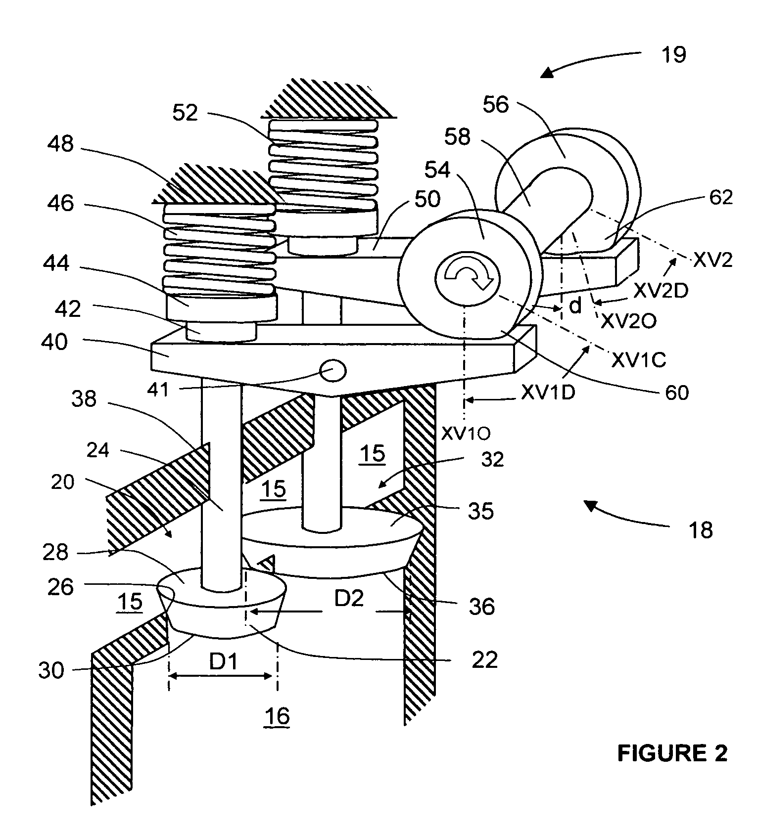
[0024]Referring now to FIG. 2, a preferred embodiment of the invention provides a crossover valve system 18. The system 18 comprises a first crossover valve 20 of a smaller diameter D1 and a second crossover valve 32 of a larger diameter D2.

[0025]The crossover valve system 18 is part of a split cycle engine, the entirety of which is not shown in FIG. 2, especially but not limited to those disclosed in U.S. Pat. No. 6,543,225, No. 6,952,923, and No. 6,986,329 and US Patent Applications 2009 / 0038598-A 1, 2009 / 0039300-A 1, and 2009 / 0044778-A 1. The split-cycle engine includes a crankshaft revolving about a crankshaft axis; at least one compression piston slideably received within a corresponding compression cylinder and operably connected to the crankshaft such that the compression piston reciprocates through an intake stroke and a compression stroke during a single rotation of the crankshaft or a thermodynamic cycle; at least one power piston slideably received within a corresponding ...


PUM


Abstract

Crossover valve systems and corresponding methods offer an effective means to overcome large opening pressure force, or provide reasonable gas flow area, or both. In an exemplary embodiment, a crossover valve system for a split-cycle engine having a power cylinder and a crossover passage comprises first and second crossover valves, each valve opening outwardly away from the power cylinder and providing fluid communication between the power cylinder and the crossover passage, with the diameter of the second crossover valve being larger than the diameter of the first crossover valve; and an actuation mechanism operative to open the first crossover valve, then the second crossover valve after a predetermined delay to allow a certain rise in the pressure inside the power cylinder, resulting in much smaller differential pressure forces across the crossover valves, larger flow areas, or both.

Description

REFERENCE TO RELATED APPLICATION[0001]This application claims priority to Provisional U.S. Patent Application No. 61 / 271,607, file on Jul. 23, 2009, the entire content of which are incorporated herein by reference.FIELD OF THE INVENTION[0002]This invention relates generally to crossover valve systems for a split-cycle engine and corresponding methods for controlling such systems, and in particular, to systems offering effective solutions to large opening differential pressure force.BACKGROUND OF THE INVENTION[0003]A split four-stroke cycle internal combustion engine is described in, but not limited by, U.S. Pat. Nos. 6,543,225, 6,952,923 and 6,986,329. It includes at least one power piston and a corresponding expansion or power cylinder, and at least one compression piston and a corresponding compression cylinder. The power piston reciprocates through a power stroke and an exhaust stroke of a four-stroke cycle, while the compression piston reciprocates through an intake stroke and a...

Claims


Application Information

Patent Timeline
Patent Type & Authority Patents(United States)
IPC IPC(8): F01L1/34
CPCF01L3/00F01L2003/258
Inventor LOU, ZHENG
Owner LGD TECH LLC
Learn More