
Domain wall movement on magnetic strip tracks

a magnetic strip and domain wall technology, applied in the direction of instruments, domain wall position/motion measurement, magnetic property measurement, etc., can solve problems such as the difficulty of accurately determining the position, and achieve the effect of accurate determination of the position of the domain wall

Inactive Publication Date: 2012-09-18
SEAGATE TECH LLC
View PDF5 Cites 1 Cited by
  • Summary
  • Abstract
  • Description
  • Claims
  • Application Information

AI Technical Summary

Benefits of technology

Enables precise control and determination of domain wall position and rotation, independent of magnetic material properties, facilitating high-density data storage and rotational measurements for applications in consumer electronics and navigation.

Problems solved by technology

However, it is a challenge to accurately determine the position of a domain wall.

Method used


Image

  • Domain wall movement on magnetic strip tracks
  • Domain wall movement on magnetic strip tracks
  • Domain wall movement on magnetic strip tracks

Examples


Embodiment Construction

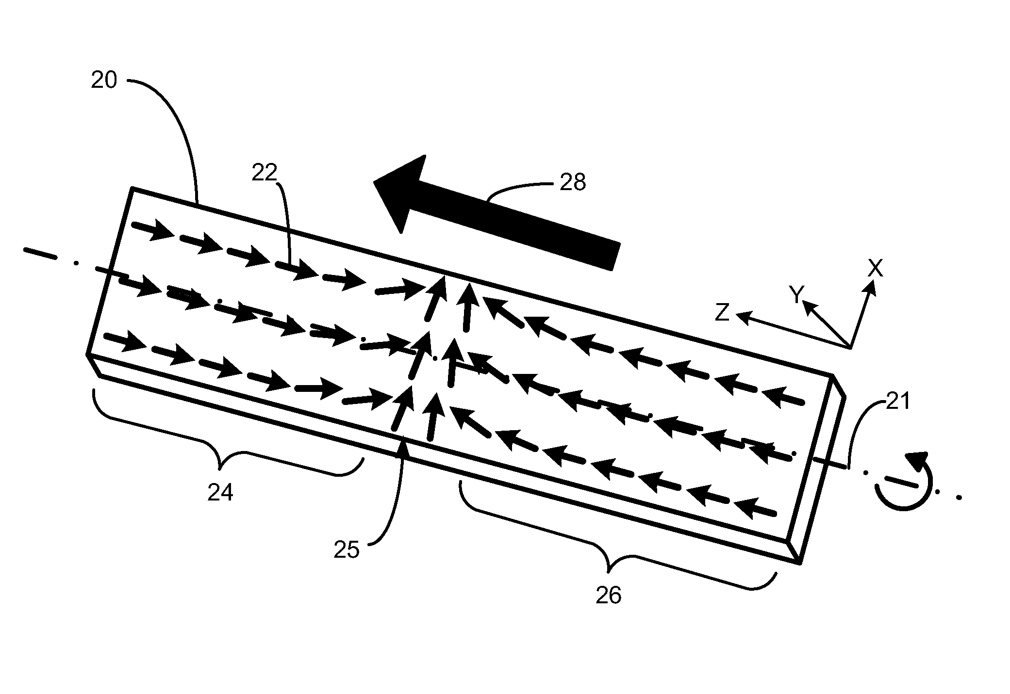
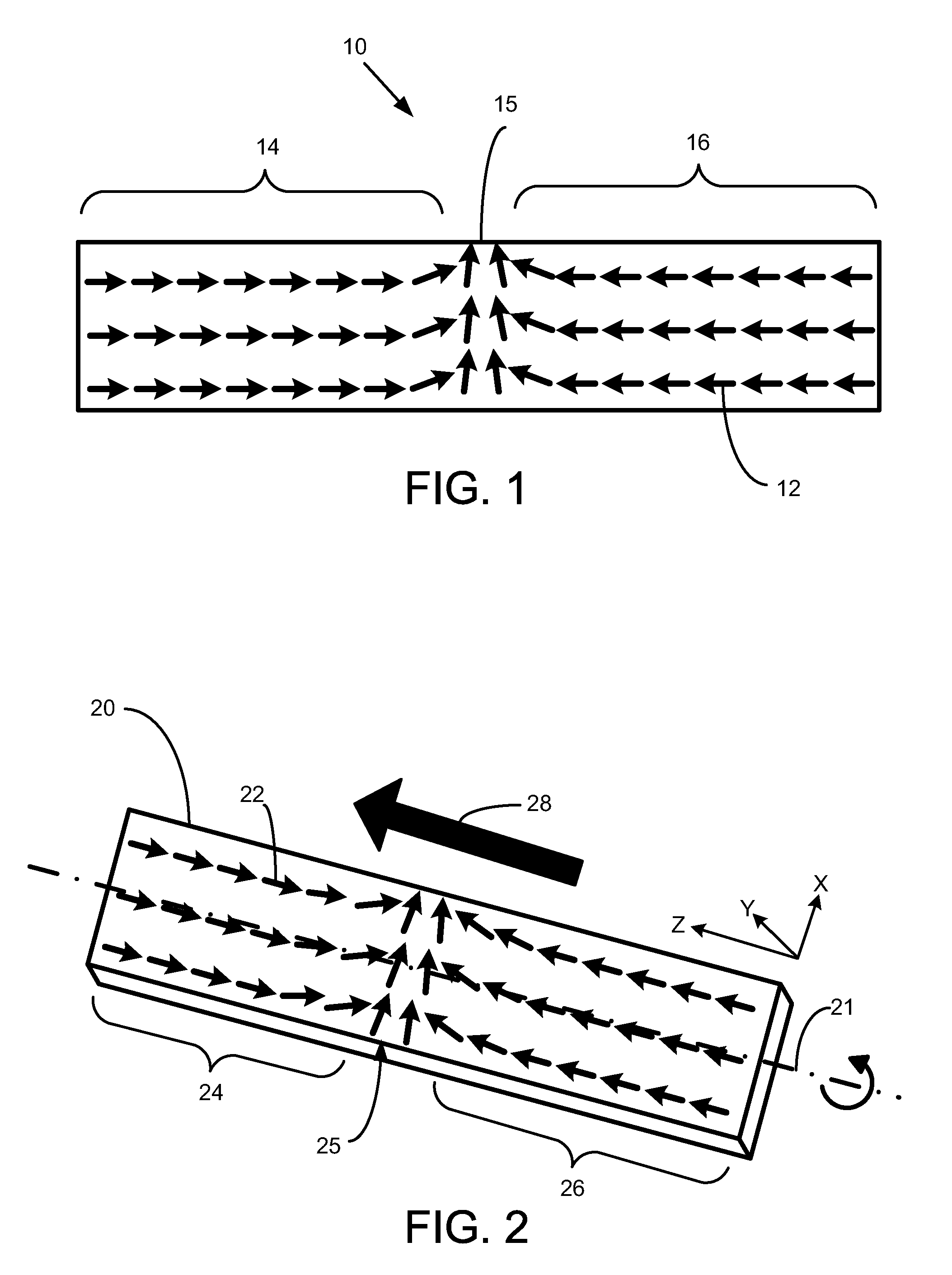
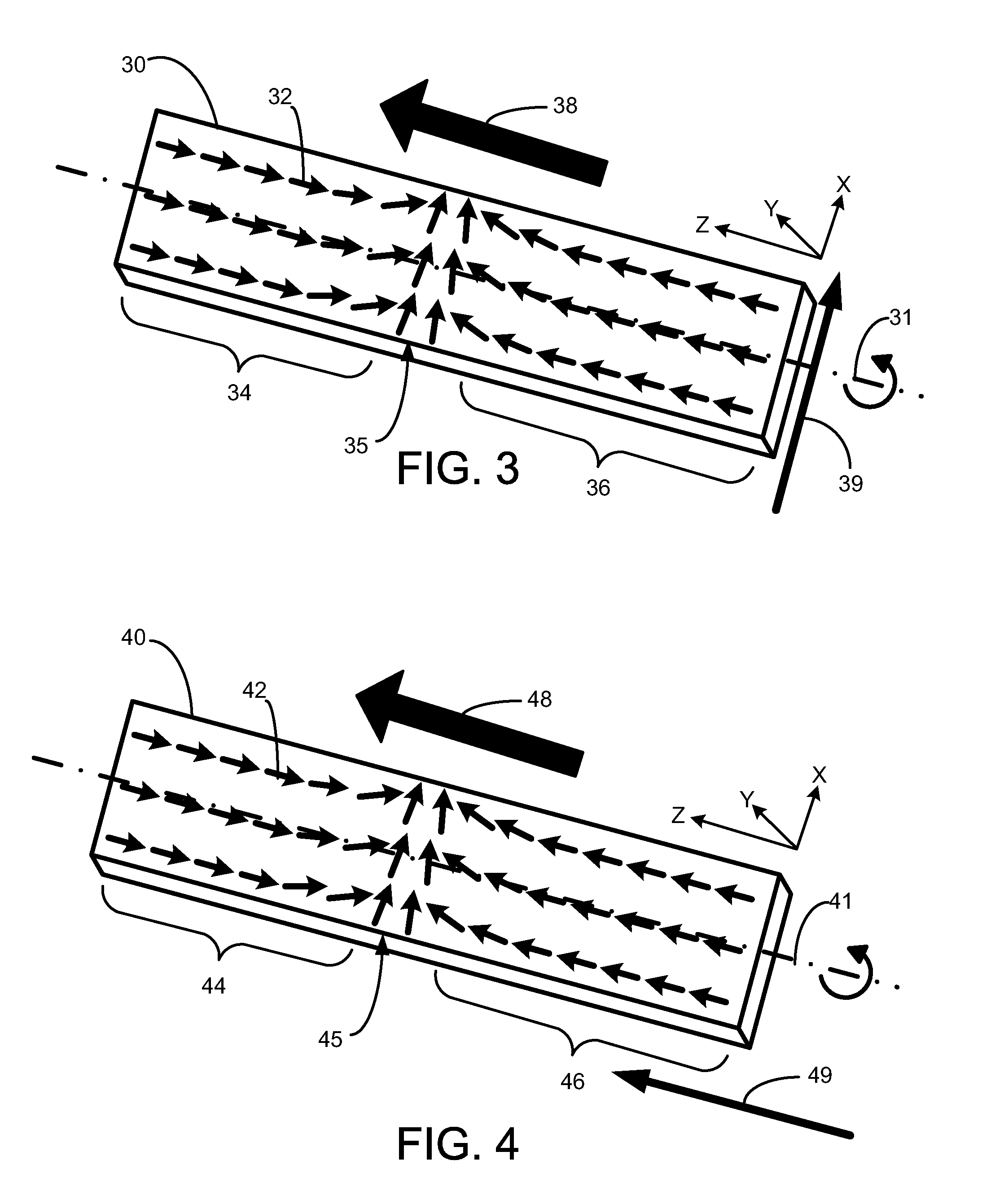
[0019]The present disclosure is to systems that utilize domain wall motion in a magnetic strip track. The track is magnetized in small sections, referred to herein as domains, in one direction or another. Between adjacent domains are domain walls, which is a concentration of a change in magnetism from one direction to another in a very small space. In a magnetic material with domain walls, a current passed across the domain wall moves the domain wall in the direction of the electron current flow. As the current passes through a domain wall, the current exerts spin torque on the domain wall and then drags the domain wall to move with it.

[0020]In the following description, reference is made to the accompanying set of drawings that form a part hereof and in which are shown by way of illustration several specific embodiments. It is to be understood that other embodiments are contemplated and may be made without departing from the scope or spirit of the present disclosure. The following ...


PUM


Abstract

Magnetic shift tracks or magnetic strips, to which application of a rotating magnetic field or by rotation of the strip itself allows accurate determination of domain wall movement. One particular embodiment is a method of determining a position of a domain wall in a magnetic strip. The method includes applying a rotating magnetic field to the magnetic strip, the magnetic field rotating around a longitudinal axis of the magnetic strip, and after applying the magnetic field, determining a displacement of the domain wall to a second position.

Description

RELATED APPLICATIONS[0001]This application claims priority to U.S. provisional patent application No. 61 / 104,087, filed on Oct. 9, 2008 and titled “Robust Domain Wall Positioning on Magnetic Strip Tracks Through Rotational Fields” and to U.S. provisional patent application No. 61 / 104,080, filed on Oct. 9, 2008 and titled “Accurate Rotation Angle Detector Through Domain Wall Motion on Magnetic Strip Tracks”. The entire disclosure of application Nos. 61 / 104,087 and 61 / 104,080 is incorporated herein by reference.BACKGROUND[0002]In recent years, the commercial market for memory has gradually shifted from that for personal, desk top computers to consumer devices such as handheld or portable music players, communication devices, computing devices, and combinations of these features in one device. Due to the smaller and smaller size of these portable devices, memory with higher density and speed, lower power consumption, and small size is in high demand.[0003]Extensive development has been...

Claims


Application Information

Patent Timeline
Patent Type & Authority Patents(United States)
IPC IPC(8): G11C11/00
CPCG01R33/1207G01R33/1284G01R33/1292G11C19/0816
Inventor WANG, XIAOBINXI, HAIWENCHEN, YIRANYAN, YUANZHENG, JUN
Owner SEAGATE TECH LLC
Learn More