
Omnidirectional vehicle

a technology of omnidirectional vehicles and pendulums, which is applied in the direction of bicycles, transmissions, transportation and packaging, etc., can solve problems such as turning-around movements, and achieve the effect of excellent ride quality and high steering stability

Active Publication Date: 2012-09-18
HONDA MOTOR CO LTD
View PDF6 Cites 16 Cited by
  • Summary
  • Abstract
  • Description
  • Claims
  • Application Information

AI Technical Summary

Benefits of technology

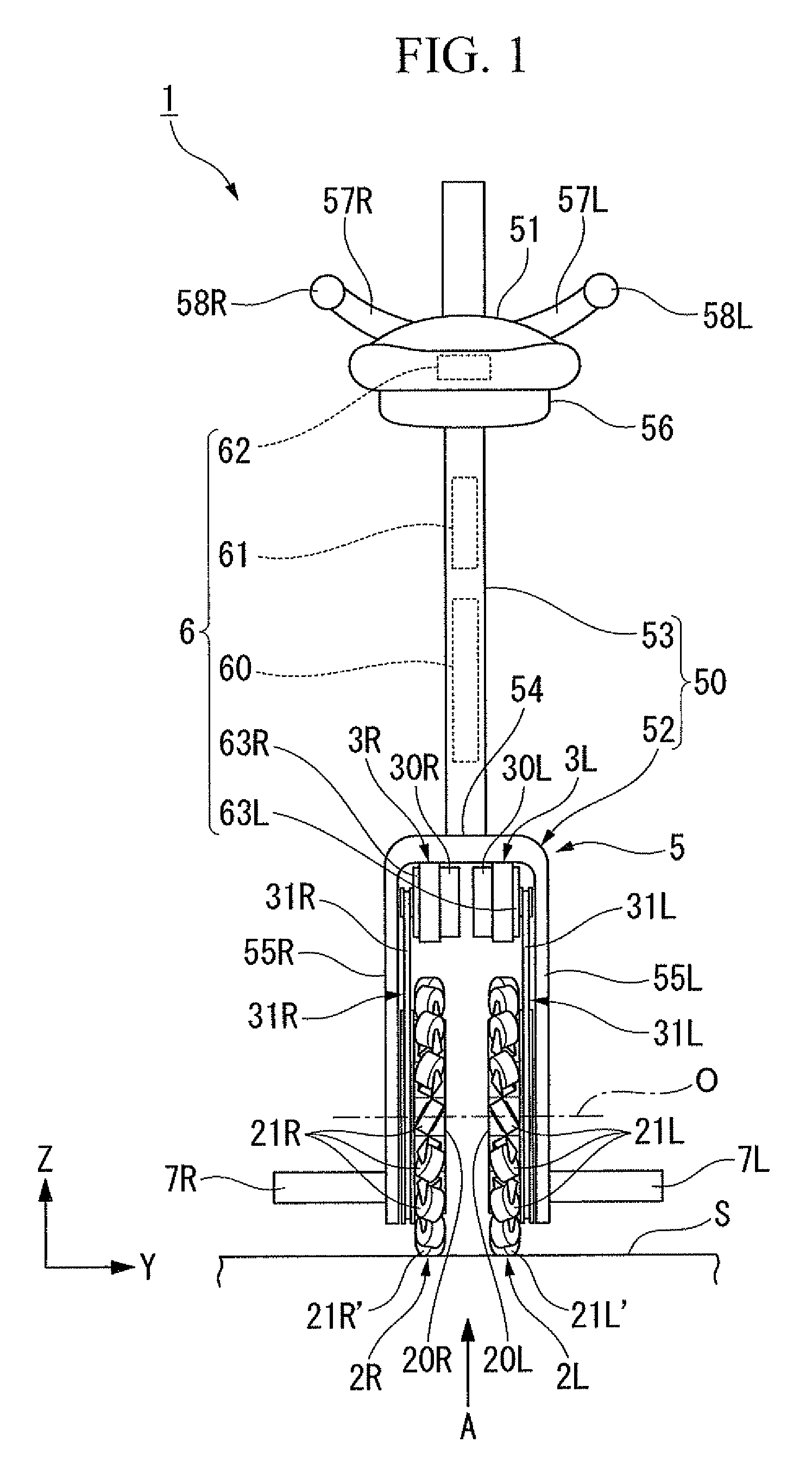
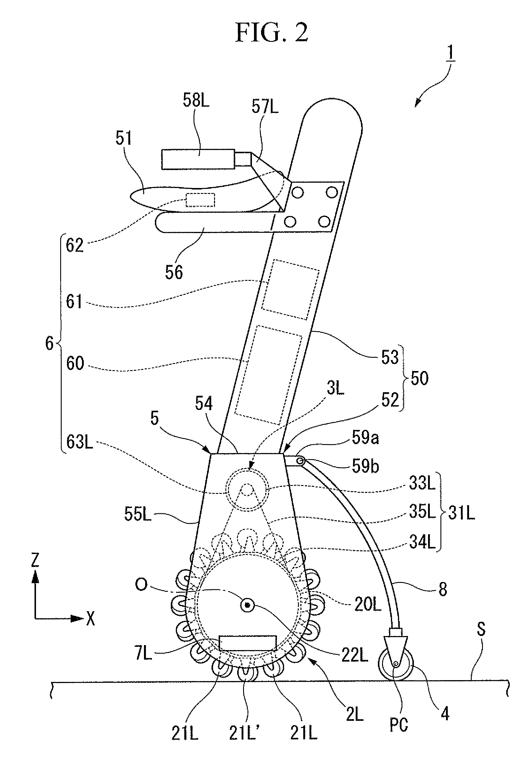
[0012]According to this omnidirectional vehicle, a vertical distance from a ground contact point of the auxiliary wheel to an extension line of the rotation axes of the free rollers in contact with the road surface is short. Therefore, when the wheel on a first side spins during traveling, the moment acting on the wheel on a second side becomes small, making it unlikely to produce a turning-around movement with the auxiliary wheel as a pivot. Furthermore, when the wheel on the first side spins in traveling in the direction of the pair of wheels seen from the auxiliary wheel, only the vector on a second side in diagonally forward direction in the wheel on the second side acts. As a result, the vehicle turns around in the second side direction. At this time, a load on the wheel on the first side (the spinning side) increases due to centrifugal force. This facilitates the wheel on the first side to be restored from the spinning state.
[0013]Therefore, according to the omnidirectional vehicle according to an embodiment of the present invention, even if a first wheel spins, the vehicle is unlikely to turn around. In addition, the spinning first wheel is likely to be restored to the ground contact position. Consequently, it is possible to achieve high steering stability and excellent ride quality.

Problems solved by technology

Therefore, when the wheel on a first side spins during traveling, the moment acting on the wheel on a second side becomes small, making it unlikely to produce a turning-around movement with the auxiliary wheel as a pivot.

Method used


Image

  • Omnidirectional vehicle
  • Omnidirectional vehicle
  • Omnidirectional vehicle

Examples


Embodiment Construction

[0018]Hereunder is a description of an embodiment of an omnidirectional vehicle according to the present invention based on the drawings.

[0019]First, a structure of the omnidirectional vehicle in the present embodiment will be described.

[0020]As shown in FIG. 1 and FIG. 2, the omnidirectional vehicle in the present embodiment (hereinafter, referred to simply as “vehicle 1”) is a vehicle movable on a road surface S in all directions (two-dimensional all directions including the forward-rearward direction and the left-right direction). The vehicle 1 is an inverted pendulum type electromotive vehicle that, when a passenger seated on the vehicle 1 makes a weight shift to a desired degree in a desired direction, travels toward the direction of the weight shift at a speed in proportional to the degree of the weight shift. As a schematic structure, the vehicle 1 includes: a pair of wheels 2R, 2L disposed in parallel; drive mechanisms 3R, 3L that impart power for driving the pair of wheels ...


PUM


Abstract

An inverted pendulum type omnidirectional vehicle includes: a pair of wheels; a drive mechanism; a control apparatus; an auxiliary wheel; and a vehicle body. Each of the wheels includes: a rotation member capable of rotating about the wheel axis; a plurality of free rollers which are disposed all around an outer circumference of the rotation member, and each of which is brought into contact with a road surface at a lowest position of the rotation member and is rotatable about a rotation axis diagonal with respect to the wheel axis. The free rollers on both sides in contact with the road surface at ground contact portions each have the rotation axis extending in parallel with the road surface, and are arranged in an orientation in which a distance between the rotation axes of the free rollers is shorter toward a side of the auxiliary wheel.

Description

BACKGROUND OF THE INVENTION[0001]1. Field of the Invention[0002]The present invention relates to an inverted pendulum type omnidirectional vehicle.[0003]Priority is claimed on Japanese Patent Application No. 2009-217791, filed on Sep. 18, 2009, the contents of which are incorporated herein by reference.[0004]2. Description of the Related Art[0005]Conventionally, omnidirectional type carts such as described in, for example, Japanese Unexamined Patent Application, First Publication No. 2004-344435 have been proposed. Specifically, this cart includes: four wheels, each made of a Mecanum wheel; drive mechanisms that rotate each of the wheels about a wheel shaft thereof; a control apparatus that controls the drive mechanisms; and a vehicle body to which a plurality of wheels are attached and which receives the load of a passenger. The wheels (Mecanum wheels) each include: a rotation member that is disposed substantially vertical to a road surface and that is rotatable about a wheel shaft...

Claims


Application Information

Patent Timeline
Patent Type & Authority Patents(United States)
IPC IPC(8): B62M13/00
CPCB62K1/00B62K3/007B62K11/007
Inventor TAKENAKA, TORU
Owner HONDA MOTOR CO LTD
Learn More