
Transmission system

a transmission system and transmission system technology, applied in data switching networks, multiplex communication, hybrid switching fabrics, etc., can solve the problems of large transmission delay times, reduced reliability, and loss of advantages of asynchronous data, so as to suppress transmission delays and fluctuations, suppress transmission delays, and high data transfer reliability

Inactive Publication Date: 2012-09-11
FUJITSU LTD
View PDF23 Cites 4 Cited by
  • Summary
  • Abstract
  • Description
  • Claims
  • Application Information

AI Technical Summary

Benefits of technology

The invention relates to a transmission system that can reliably transfer data that includes both synchronous and asynchronous data. The system has multiple switches and a distribution control unit that can identify the type of data and transfer it to the appropriate switch. The system also has a tag insertion unit and a multiplexing unit that can handle both synchronous and asynchronous data. The system can prioritize processing of synchronous data and reduce delays in transferring it. The invention can also reduce the load on switches and improve the transfer of data.

Problems solved by technology

Such functions cannot be incorporated into a time-division switch, and so in the end only simple functions for transferring data can be used with asynchronous data, and the advantages of asynchronous data are largely lost.
Further, because of the complexity of relay processing, reliability is reduced, and in addition this method effectively entails storage communication, so that transmission delay times tend to be large.
However, if this method is used, all unrelated top-priority packets (frame-converted synchronous data) not addressed to its own station are sent to the packet switch, resulting in reduced operating capacity of the packet switch, so that the problems of sharply reduced communication speed of asynchronous data not subjected to prioritized processing and increased discarding of packets arise.
Such a third method of the prior art requires placement of both a packet switch and a time-division switch, and is disadvantageous in terms of both circuit scale and implementation efficiency; in addition, due to the different frame formats of data handled by the packet switch and the time-division switch, the following problems arise.
Hence the processing load on both switches becomes excessive; in particular, the problems of the above-described second method of the prior art remain.
That is, in the packet switch, the problems of greatly diminished communication speed of asynchronous data and of an increase in the discarding of packets occurs.

Method used


Image

  • Transmission system
  • Transmission system
  • Transmission system

Examples


Embodiment Construction

[0050]Below, aspects of the invention are explained referring to the drawings. However, the aspects do not limit the technical scope of the invention.

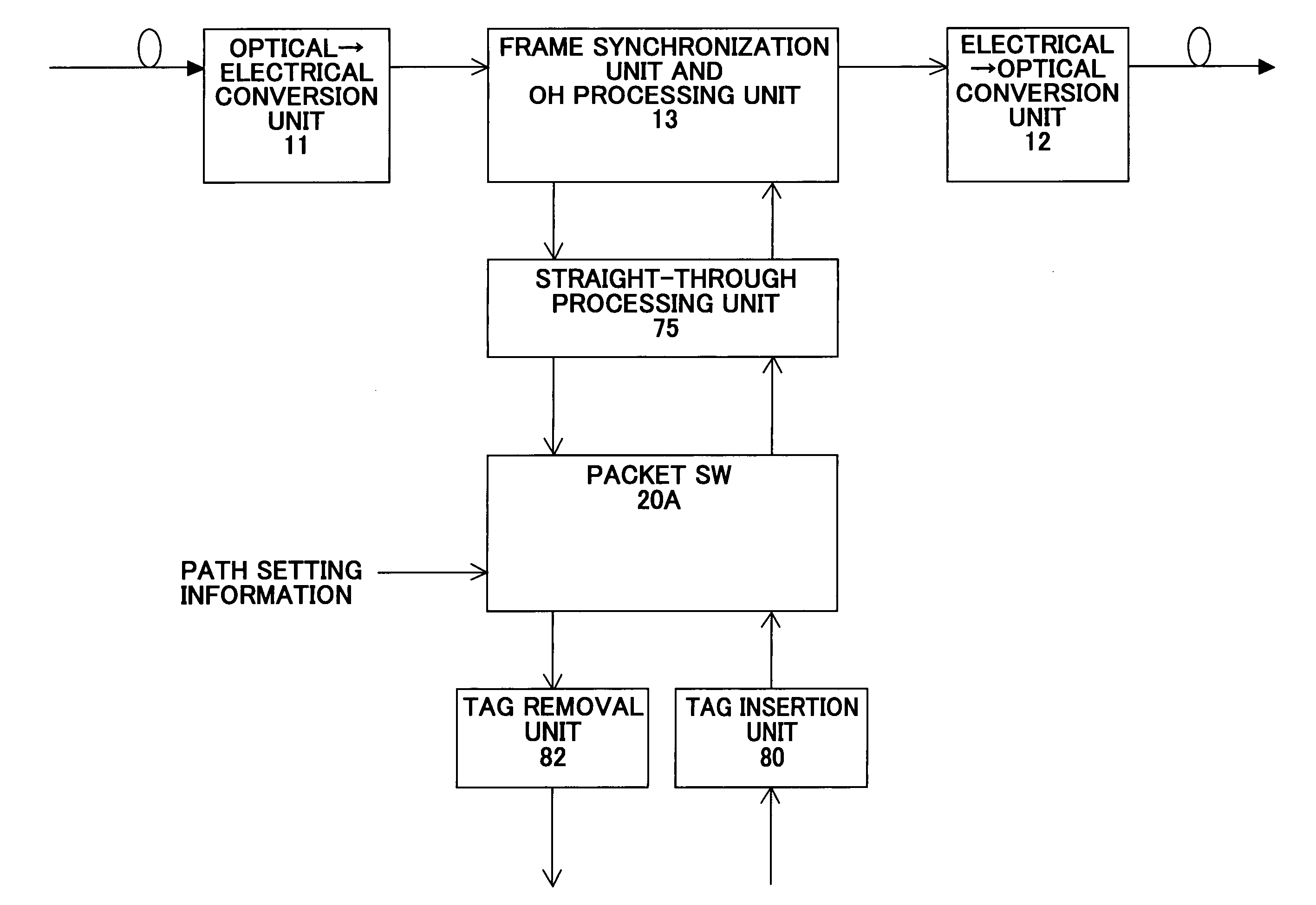
[0051]FIG. 5 shows a first configuration example of the transmission system of an aspect of the invention. This first configuration example is the configuration of FIG. 4, comprising a distribution control unit 70 and a tag insertion unit 80 (an inclusive term for the tag insertion units 80A and 80B), which are characteristic of this invention.

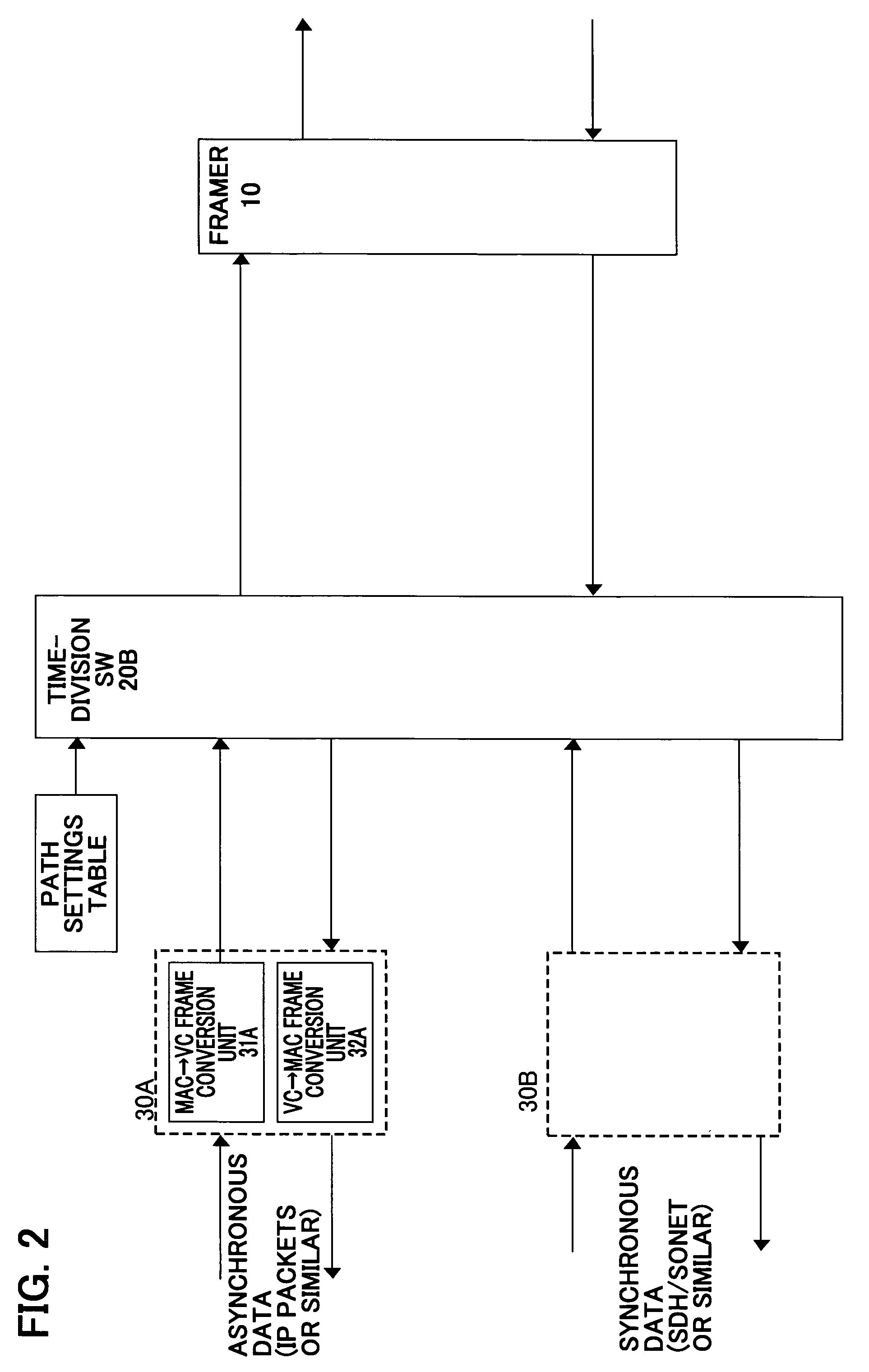
[0052]The packet switch 20A for asynchronous communication and the time-division switch 20B for synchronous communication are arranged in parallel, and data output from the two switches in the direction of the framer (node) 10 is multiplexed by the multiplexing unit 50 and sent to the framer 10. The frame conversion unit 60A converts frames of asynchronous data into frames of synchronous data in order to unify the asynchronous data frames and synchronous data frames as synchronous data frames. Wh...


PUM


Abstract

A transmission system is provided which multiplexes and transmits synchronous data and asynchronous data, while maintaining the communication quality required of synchronous data and of asynchronous data respectively. A tag having information used to identify the data as synchronous data or as asynchronous data is added to both synchronous data and to asynchronous data. Tags added to each data item are extracted, and based on the information contained in the tag, each data item is identified as synchronous data or as asynchronous data, and synchronous data is transferred to a time-division switch, while asynchronous data is transferred to a packet switch.

Description

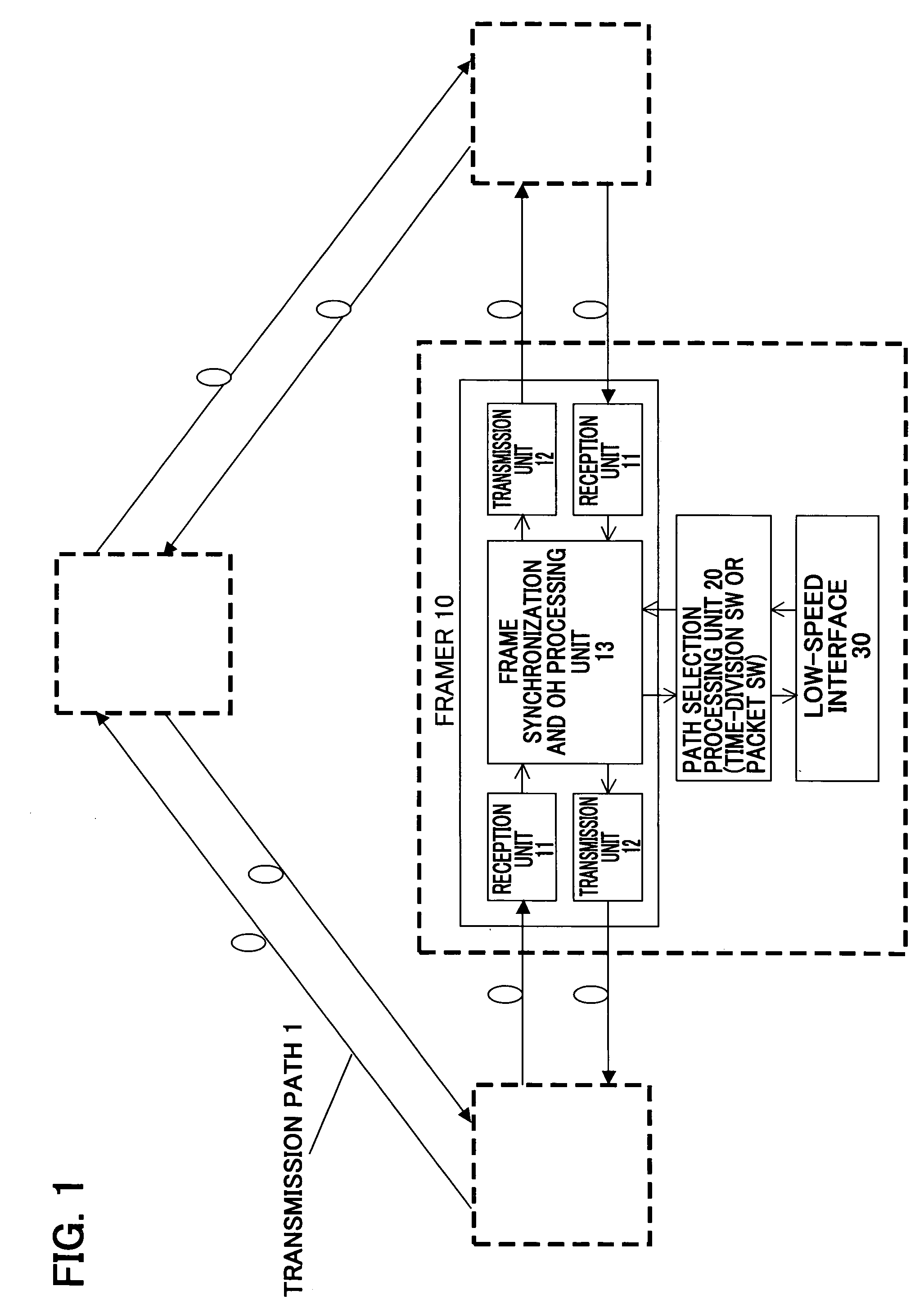
CROSS-REFERENCE TO RELATED APPLICATIONS[0001]This application is based upon and claims the benefit of priority from the prior Japanese Patent Application No. 2006-81879, filed on Mar. 24, 2006, the entire contents of which are incorporated herein by reference.BACKGROUND OF THE INVENTION[0002]1. Field of the Invention[0003]The present invention relates to a transmission system capable of accommodating both a synchronous communication system such as SONET / SDH and an asynchronous communication system such as TCP / IP, and in particular relates to a transmission system which is capable of transmitting synchronous-system data without transmission delays or fluctuations thereof, while maintaining path processing for asynchronous-system data.[0004]2. Description of the Related Art[0005]In a synchronous communication system such as SONET (Synchronous Optical NETwork) / SDH (Synchronous Digital Hierarchy), a high-speed transmission standard based on optical fiber, time-division switches multiple...

Claims


Application Information

Patent Timeline
Patent Type & Authority Patents(United States)
IPC IPC(8): H04L12/66H04J3/00H04L12/42H04L12/64H04L12/70
CPCH04J3/08H04L12/40071H04J3/1617H04J2203/0042H04L2012/6405
Inventor IZUMI, FUTOSHI
Owner FUJITSU LTD
Learn More