
Digital radio frequency tranceiver system and method

a digital radio frequency tranceiver and digital technology, applied in the field of radio frequency transceivers, can solve problems such as possible service and maintenance problems of cryocoolers, and achieve the effect of correcting non-idealities that limit practical performan

Active Publication Date: 2012-09-04
HYPRES
View PDF14 Cites 39 Cited by
  • Summary
  • Abstract
  • Description
  • Claims
  • Application Information

AI Technical Summary

Benefits of technology

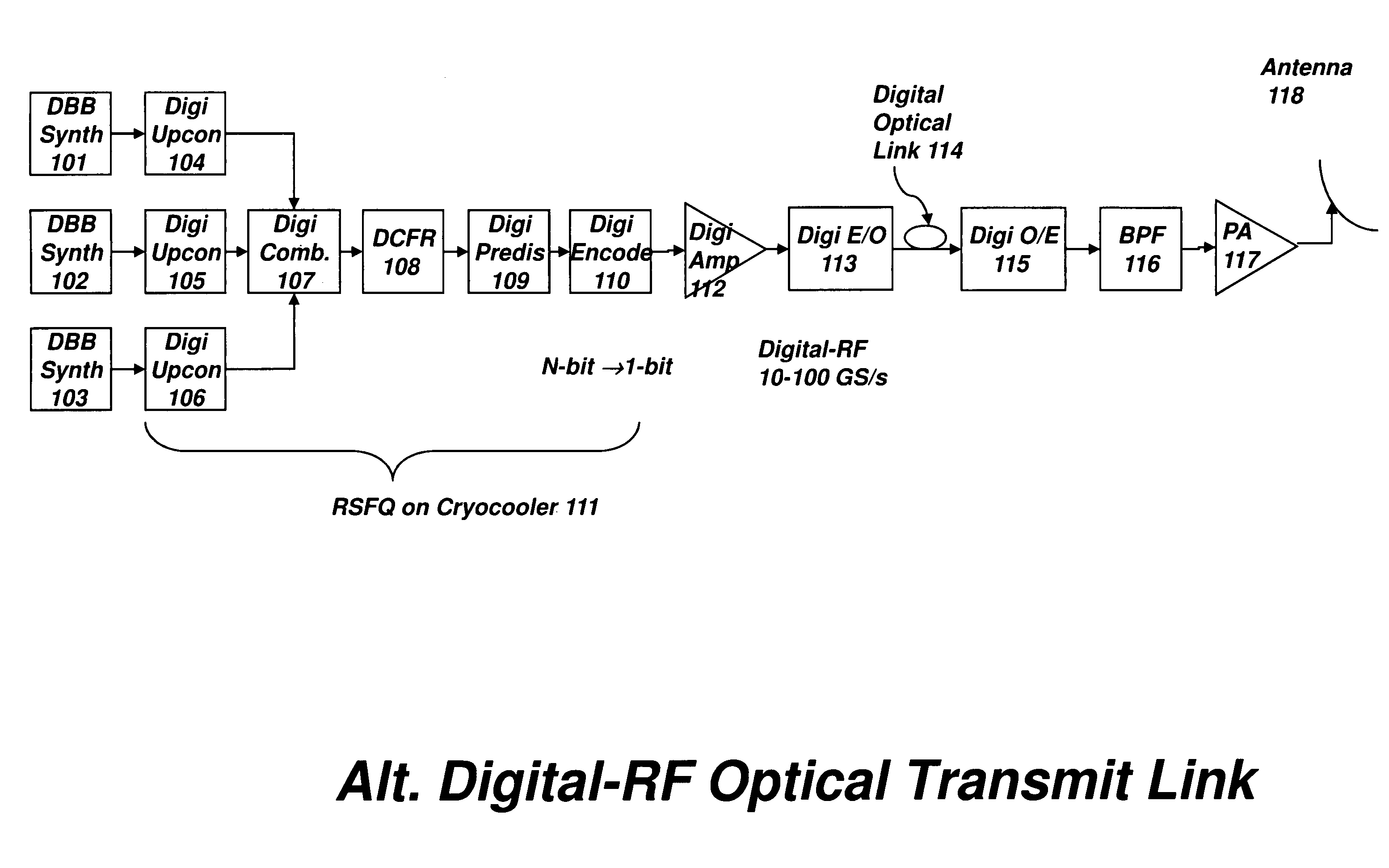
"The present invention provides a new system architecture that combines three technologies: superconducting RSFQ circuits, microwave-frequency optical links, and broadband semiconductor power amplifiers. This hybrid system addresses the non-idealities of each technology and corrects for non-linearities in amplifiers and electro-optic converters. The system is designed to be efficient and effective in communication of signals from the antenna electronics system to a remote location. The invention also addresses the issue of frequency translation between analog radio frequency interfaces and digital electronics, which can cause distortion and degradation of wideband radio frequency signals. The patent text provides options for the transmit channel, including a direct analog signal communication, a baseband or intermediate frequency communication link, and a digital communication link. The invention aims to improve the performance and reliability of wireless communication systems."

Problems solved by technology

In addition, the cryocooler presents a possible service and maintenance issue, and a preference may therefore exist to have such a cryocooler located off an antenna, and, for example, in a base station located on the ground, or rooftop, or otherwise some distance from the antenna structure.

Method used


Image

  • Digital radio frequency tranceiver system and method
  • Digital radio frequency tranceiver system and method
  • Digital radio frequency tranceiver system and method

Examples


Embodiment Construction

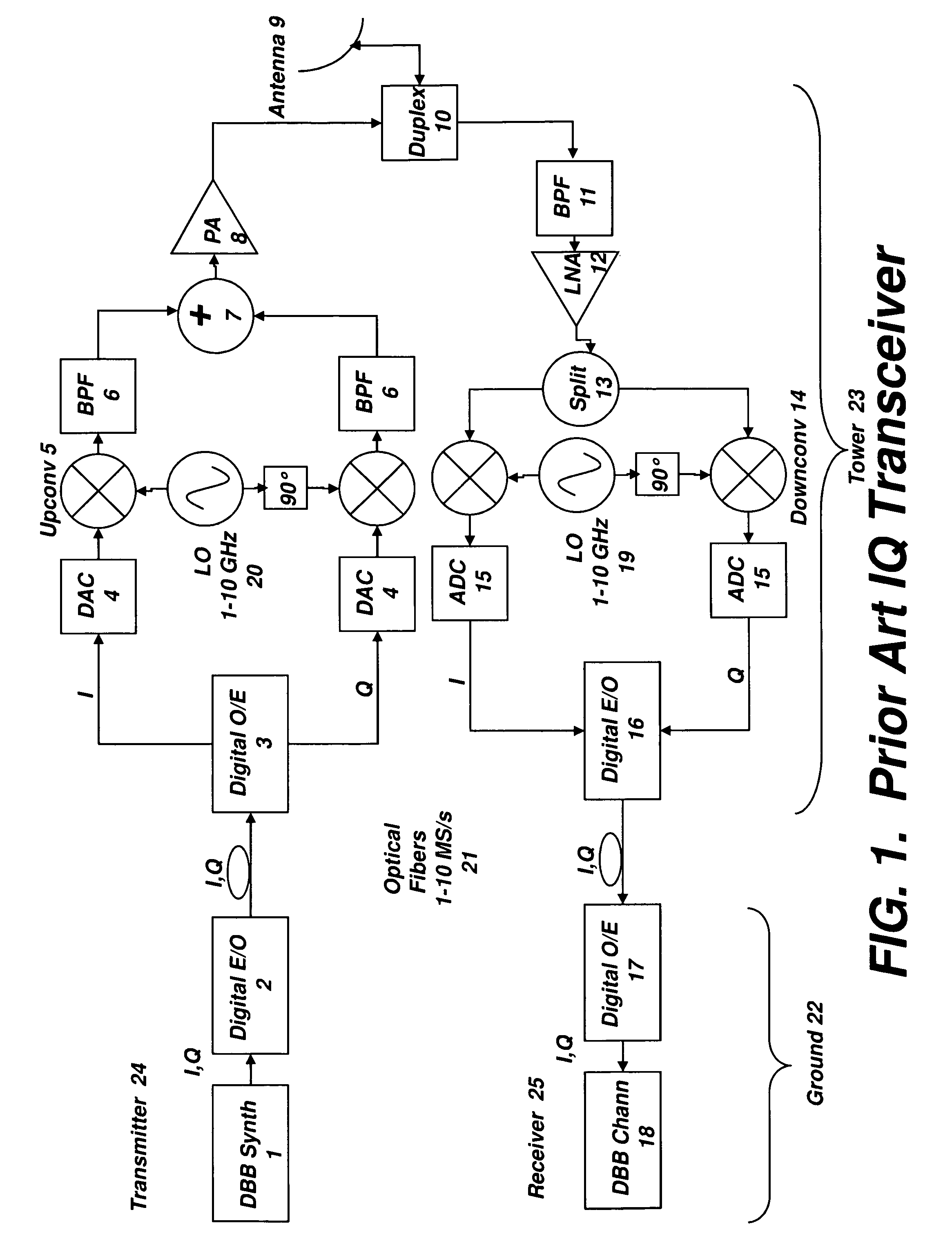
[0099]A block diagram of a modern wireless basestation of the prior art is shown in FIG. 1. This describes a split architecture, which is partitioned into digital baseband (DBB) processing on the ground (i.e., within a base station module) and analog RF processing on the tower. A version of in-phase and quadrature (IQ) receiver and transmitter are shown here, although other variants known in the art may alternatively be applied. Thus, it should be understood that FIG. 1 is simplified, and, for example, portions of the electronics may be duplicated.

[0100]Consider first the transmitter, where the DBB Synthesizer might, for example, generate an OFDM (orthogonal frequency domain multiplexed) signal that is up to a few MHz in bandwidth, comprising many narrow band signals, properly timed and encoded. This digital signal is then used to modulate a diode laser or optical interferometer, and the optical signal is coupled into an optical fiber that is sent up the tower. Optical fibers genera...


PUM


Abstract

A transceiver architecture for wireless base stations wherein a broadband radio frequency signal is carried between at least one tower-mounted unit and a ground-based unit via optical fibers, or other non-distortive media, in either digital or analog format. Each tower-mounted unit (for both reception and transmission) has an antenna, analog amplifier and an electro-optical converter. The ground unit has ultrafast data converters and digital frequency translators, as well as signal linearizers, to compensate for nonlinear distortion in the amplifiers and optical links in both directions. In one embodiment of the invention, at least one of the digital data converters, frequency translators, and linearizers includes superconducting elements mounted on a cryocooler.

Description

RELATED APPLICATIONS[0001]The present application claims the benefit of priority of Provisional Patent Application 61 / 035,932, filed, Mar. 12, 2008, the entirety of which is expressly incorporated herein by reference.FIELD OF THE INVENTION[0002]The present invention is directed towards radio-frequency (RF) transceivers, and more specifically towards transceivers that use direct digitization of RF signals, and digital processing thereof.BACKGROUND OF THE INVENTION[0003]A simple RF signal consists of a narrowband baseband signal which is modulated onto a high-frequency RF carrier. A more complex, broader bandwidth RF signal may consist of multiple narrowband signals modulated on similar RF carriers. A conventional RF digital data receiver uses an analog mixer and local oscillator (LO) to translate the signal from the carrier to a lower frequency, the baseband or intermediate frequency (IF), where it is then typically digitized and further signal extraction is performed in the digital ...

Claims


Application Information

Patent Timeline
Patent Type & Authority Patents(United States)
IPC IPC(8): H04B10/00
CPCH04L27/2096H04B10/2575H04B10/697H04B10/25752H04B10/40H04B10/5561
Inventor GUPTA, DEEPNARAYANMUKHANOV, OLEGHITT, RICHARD E.
Owner HYPRES
Learn More