Multi-phase voltage regulator module and method controlling the same

a voltage regulator and multi-phase technology, applied in the direction of electric variable regulation, process and machine control, instruments, etc., can solve the problems of relative low efficiency and more unnecessary power was

Active Publication Date: 2012-09-04
ASUSTEK COMPUTER INC
View PDF6 Cites 4 Cited by
  • Summary
  • Abstract
  • Description
  • Claims
  • Application Information

AI Technical Summary

Problems solved by technology

However, more phases in a multi-phase VRM also brings more unnecessary power waste due to the impedance factor resulted in the multi-phase VRM itself.
Moreover, according to the related research, the efficiency is relative low if the multi-phase VRM is operated at a relative light load.

Method used


Image

  • Multi-phase voltage regulator module and method controlling the same
  • Multi-phase voltage regulator module and method controlling the same
  • Multi-phase voltage regulator module and method controlling the same

Examples


first embodiment

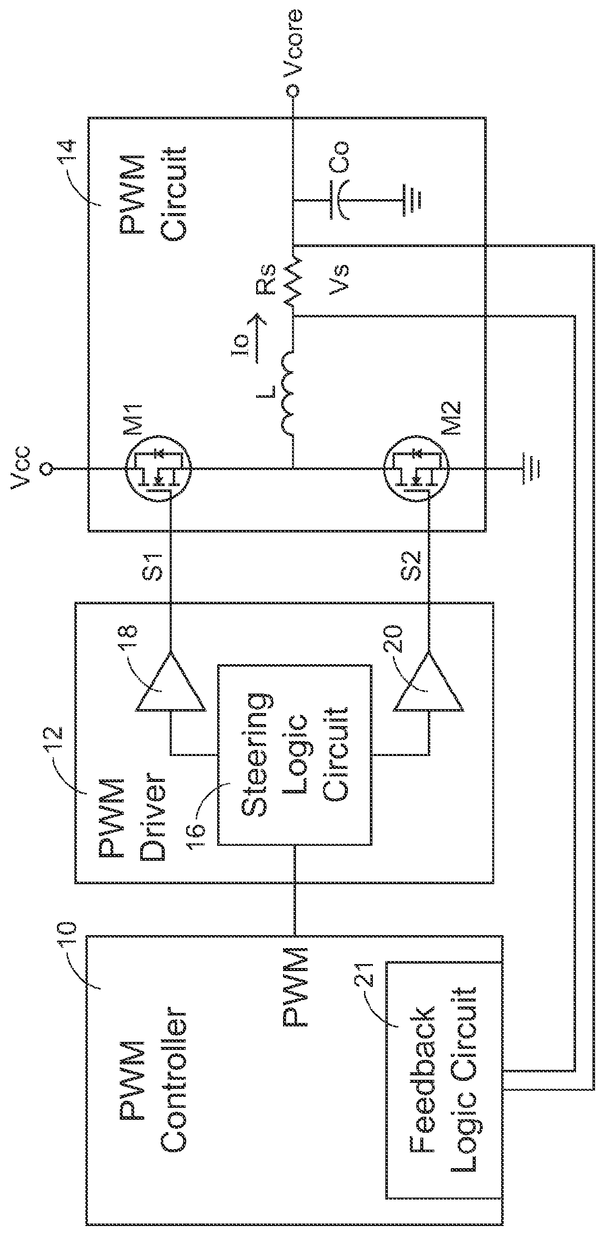
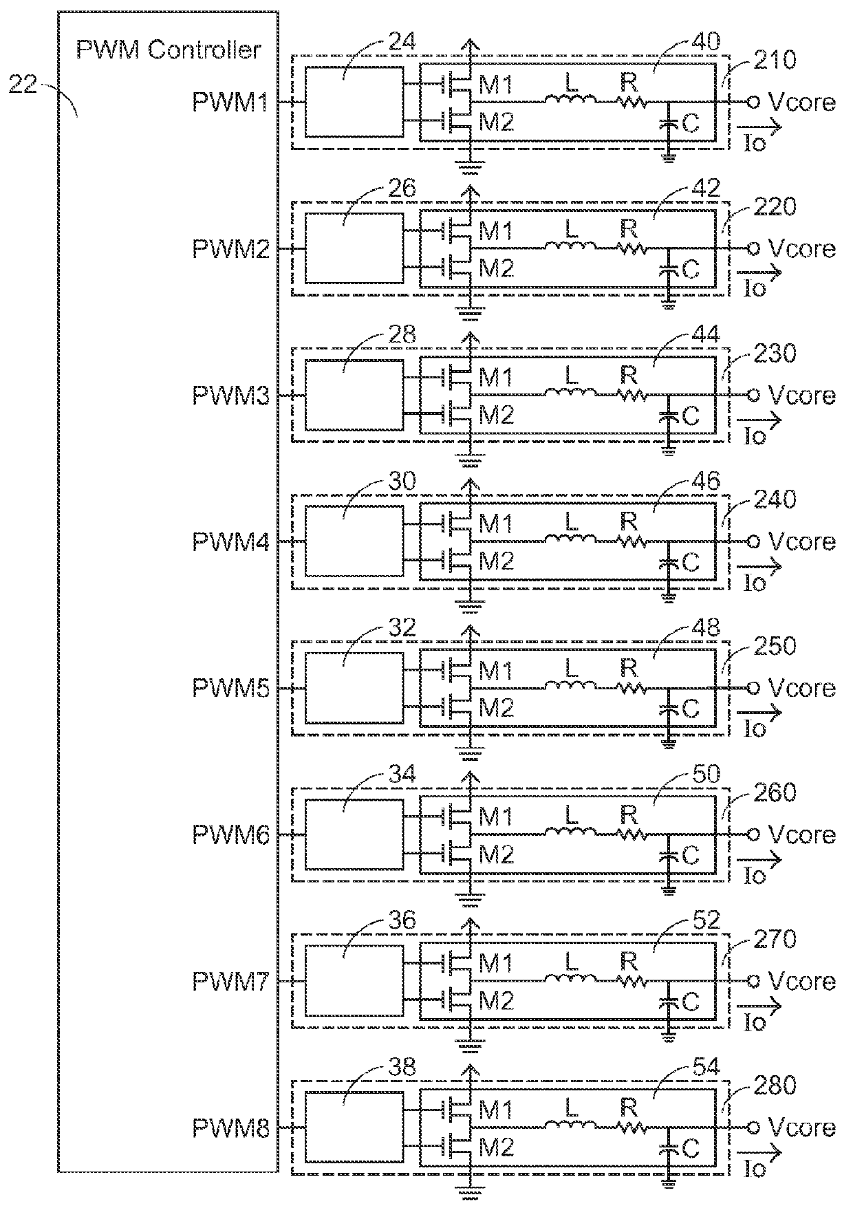
[0025]FIG. 4 is a functional block diagram depicting a multi-phase VRM of the present invention (only an eight-phase VRM is took as an example). The eight-phase VRM comprises a PWM controller 56, eight PWM drivers (58, 60, 62, 64, 66, 68, 70, 72), and eight PWM circuits (74, 76, 78, 80, 82, 84, 86, 88). Furthermore, each of the PWM circuit (74, 76, 78, 80, 82, 84, 86, 88) comprises two power FETs (M1, M2) and a RLC circuit. Furthermore, eight PWM signals (PWM1˜PWM8) are transmitted to the eight PWM drivers (58, 60, 62, 64, 66, 68, 70, 72) respectively from the PWM controller 56. Furthermore, the PWM controller 56 comprises a controlling unit 562 having an input end (in) connected to an output end of a load detect circuit (not shown), where the controlling unit 562 is used for outputting a phase-control signal to determine whether outputting the eight PWM signals (PWM1˜PWM8) or not.

[0026]Furthermore, the eight PWM drivers (58, 60, 62, 64, 66, 68, 70, 72) and the eight PWM circuits (7...

second embodiment

[0031]Furthermore, the selection of the PWM signals can be randomly determined by another mechanism. FIG. 5 is a functional block diagram depicting a multi-phase VRM of the present invention (only an eight-phase VRM is took as an example). Except replacing the PWM controller 56 (FIG. 4) by a PWM controller 90, all the rest circuits in the FIG. 5 are exactly same as the rest circuits in FIG. 4. The PWM controller 90 comprises a controlling unit 902 and an 8-bit register 904. The controlling unit 902, comprising an input end (in) connected to an output end of a load detect circuit (not shown), is used for outputting a phase-control signal for updating the value stored at the 8-bit register 904 based on the signal received at the input end (in). Furthermore, the value stored at the 8-bit register 904 is used for determining the outputting / or not outputting of the eight PWM signals (PWM1˜PWM8). Furthermore, the controlling unit 902 comprises a random-number generator 906.

[0032]In the se...


PUM


Abstract

A multi-phase voltage regulator module connects to a central processing unit and is able to operate in one of a high-load mode and a low-load mode. The multi-phase voltage regulator module comprises: a pulse-width-modulation controller generating a plurality of phase-width-modulation signals; and, a plurality of phase circuits, each of which receives a corresponding one of the phase-width-modulation signals and generates a corresponding output current to the central processing unit; wherein a first portion of the phase circuits are activated when the multi-phase voltage regulator module is operated in the low-load mode at a first time, and, a second portion of the phase circuits are activated when the multi-phase voltage regulator module is operated in the low-load mode at a second time, the first portion being non-identical to the second portion.

Description

FIELD OF THE INVENTION[0001]The present invention relates to a multi-phase voltage regulator module (VRM), and more particularly to a multi-phase VRM capable of operating with a variable active or inactive phase number.BACKGROUND OF THE INVENTION[0002]Basically, the central processing unit (CPU) of a computer system is not directly powered by a power supply. Because the intensity of the core voltage (Vcore) required by the CPU is varied with the actual load of the CPU, the intensity of the core voltage (Vcore) may change vary sharply according to the extremely heavy load or the extremely light load on the CPU. Voltage regulator module (VRM) is very widely equipped with the computer system for providing the core voltage (Vcore) to the CPU due to the VRM is designed to quickly provide the core voltage (Vcore) according to the requirement of the CPU.[0003]FIG. 1 is a functional block diagram depicting a conventional single-phase VRM. The single-phase VRM comprises a pulse-width-modulat...

Claims


Application Information

Patent Timeline
Patent Type & Authority Patents(United States)
IPC IPC(8): G05F1/40
CPCH02M3/1584H02M2001/0032Y02B70/16Y02B70/10H02M1/0032
Inventor WU, CHAO-CHUNGCHI, CHI-PENLEE, YU-CHEN
Owner ASUSTEK COMPUTER INC
Why Eureka
Try Eureka