Overload detection in a switched mode power supply
a power supply and switching mode technology, applied in the field of switching mode power supplies, can solve the problems of losing the advantages of ccp, extreme overcurrent situation, ineffective ccp, etc., and achieves the effect of easy detection and processing, increased power rating of power supplies, and no risk of breakdown
- Summary
- Abstract
- Description
- Claims
- Application Information
AI Technical Summary
Benefits of technology
Problems solved by technology
Method used
Image
Examples
example 1
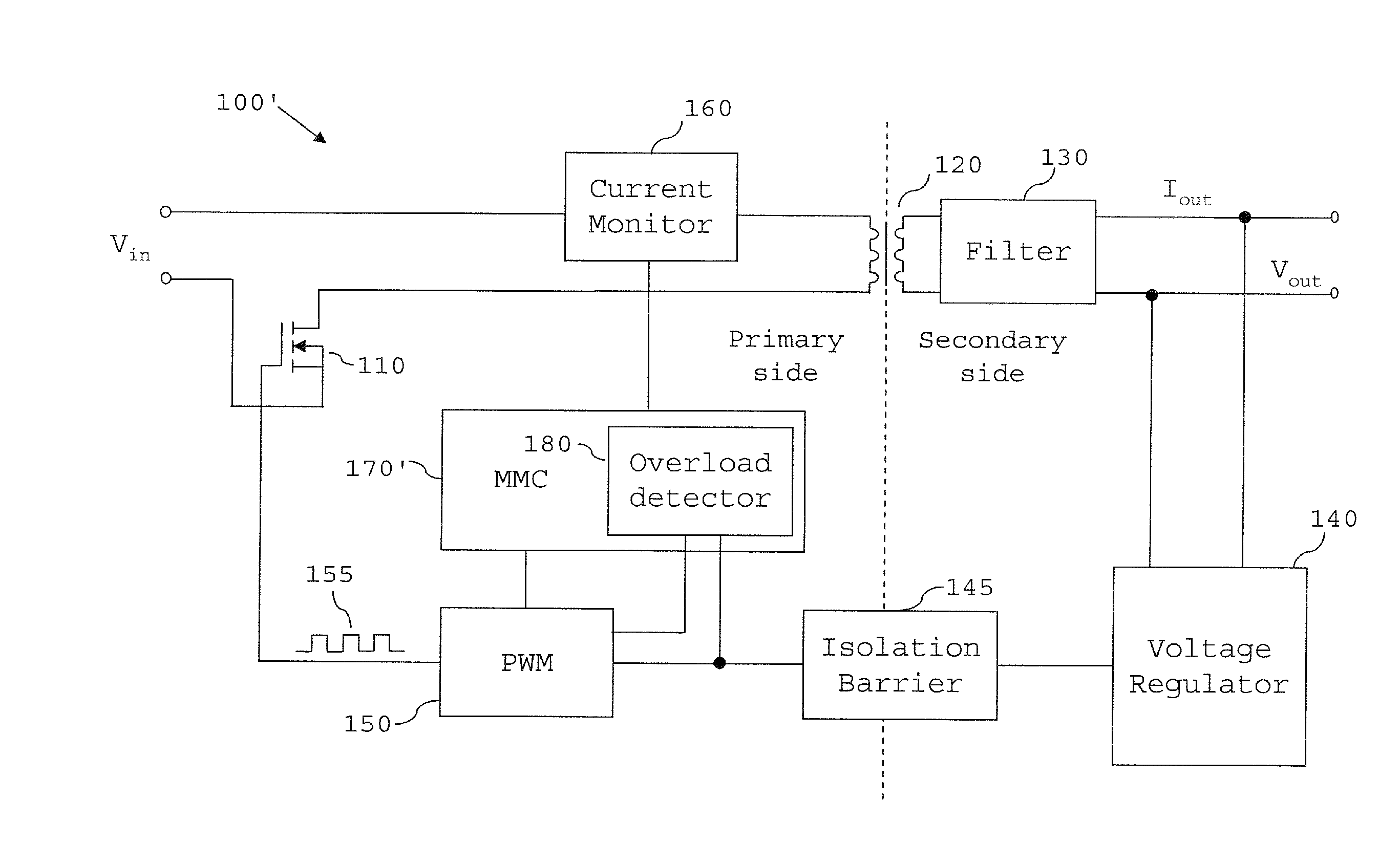
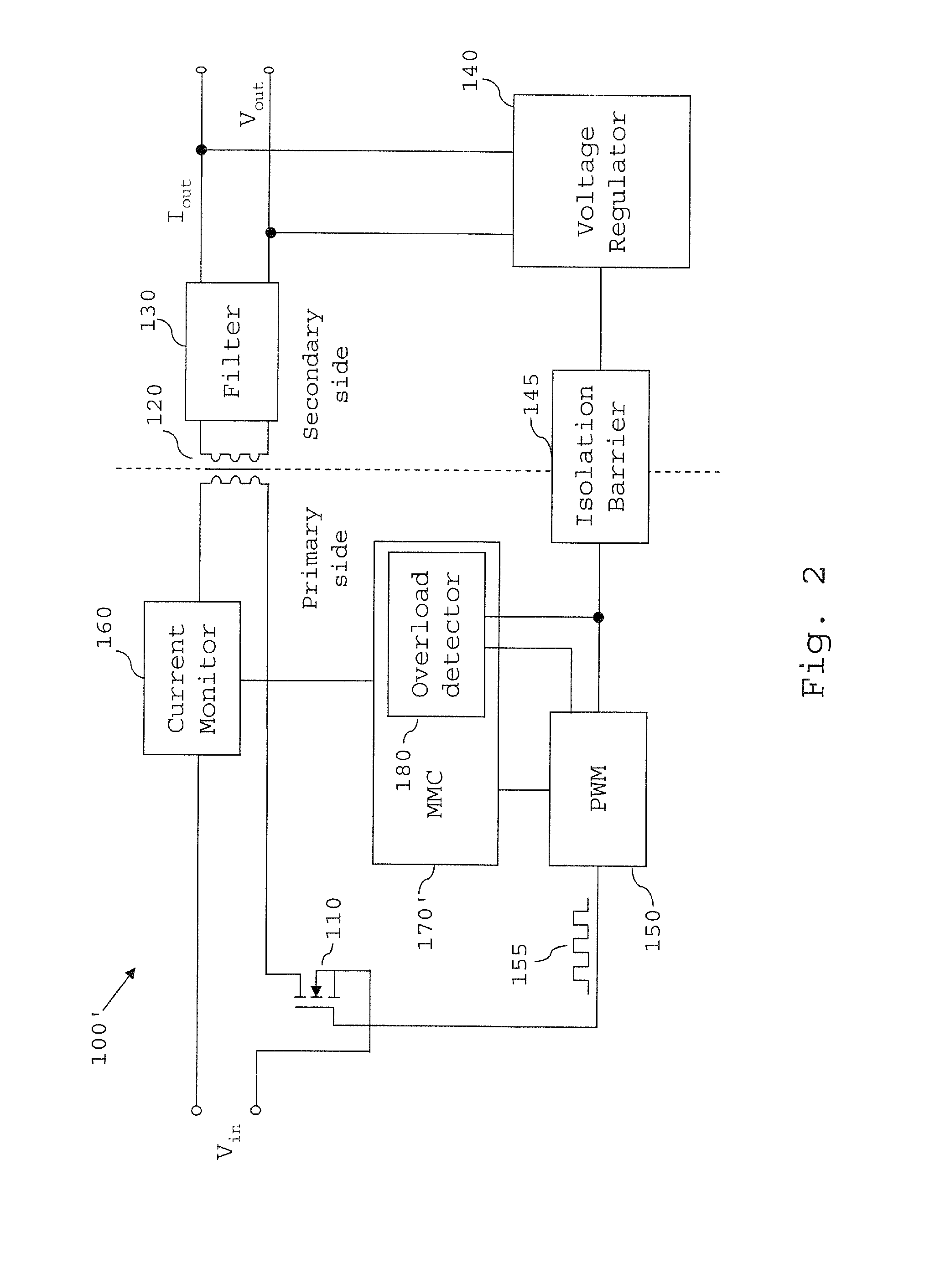
[0049]Referring first to the scheme illustrated in FIG. 6, in step S100, the overload detector 180 receives the feedback signal (error signal) via its I / O section 181 from the voltage regulator.
[0050]Then, in step S110, the overload detector 180 determines whether the feedback signal is outside a predetermined range, particularly by determining whether the COMP voltage exceeds a threshold such that it lies in the aforementioned “Fail” region shown in FIG. 5. If the feedback signal is outside the ranges encountered during normal operation (with allowance being made for transients etc. that may bring the COMP voltage within the “Dynamic” range bands), the overload detector 180 determines that the converter is in an overload state. However, if the feedback signal is not within the “Fail” region, the process loops back to step S100.
[0051]Once the overload detector has detected that the converter 100′ is an overload state in step S110, the process proceeds to step S120, in which the over...
example 2
[0052]The monitoring of the COMP signal by the overload detector 180 and its operation according to the above scheme allows the overload detector to simply and reliably detect an overload state of the DC / DC converter. Furthermore, since the COMP signal has already been subjected to filtering and amplification by the feedback circuit, the signal can be processed by the detector without the detector needing to filter or amplify the signal.
[0053]However, as noted above, short-term excursions of the feedback signal into the “Fail” region can occur if the SMPS 100′ encounters dynamic situations during its operation. For example, it may be that the power supply is charging a large capacitor, or that the speed of a fan being powered by the SMPS 100′ suddenly changes. If the power supply is to operate in an environment where such situations are expected to occur, it might be preferable to adapt the OCP mechanism of Example 1 to have a degree of tolerance to such dynamic situations. The OCP ...
example 3
[0059]A further OCP scheme will now be described with reference to FIG. 8. The operation of the overload detector 180 in accordance with this scheme reduces the risk of the detector false-triggering and unnecessarily shutting down the power supply 100′ during the power supply's start-up phase. In addition, the OCP mechanism of the present example takes into account the temperature of the power supply, which can affect the power supply's ability to safely handle over-current situations. In particular, the OCP scheme described below allows the overload detector 180 to implement protective measures more quickly at high temperatures, at which the power supply is more prone to damage when overloaded.
[0060]Similar to Example 2, the OCP scheme of the present example counts the number of COMP voltage samples that represent a COMP voltage in the “Fail” region, by increasing (or, as the case may be, decreasing) the count on a counter. When the counter is judged to have accumulated too many Fa...
PUM
 Abstract
Description
Claims
Application Information
 - R&D
- Intellectual Property
- Life Sciences
- Materials
- Tech Scout
- Unparalleled Data Quality
- Higher Quality Content
- 60% Fewer Hallucinations
Browse by: Latest US Patents, China's latest patents, Technical Efficacy Thesaurus, Application Domain, Technology Topic, Popular Technical Reports.
© 2025 PatSnap. All rights reserved.Legal|Privacy policy|Modern Slavery Act Transparency Statement|Sitemap|About US| Contact US: help@patsnap.com


