Cryostat having a magnet coil system, which comprises an under-cooled LTS section and an HTS section arranged in a separate helium tank

a technology of magnet coils and cryostats, which is applied in the direction of superconducting magnets/coils, magnetic bodies, instruments, etc., can solve the problems of evaporating helium not being able to escape quickly enough from porous materials, hts being exploded, and substantial pressure being built up in pores, etc., to achieve the effect of increasing the efficiency of cooling and operation safety, improving the efficiency of cooling, and being particularly safe to refill the tank

Active Publication Date: 2012-08-28
BRUKER BIOSPIN +1
View PDF6 Cites 5 Cited by
  • Summary
  • Abstract
  • Description
  • Claims
  • Application Information

AI Technical Summary

Benefits of technology

[0013]All these effects can be prevented with the cryostat configuration in accordance with the invention. The HTS section or sections of the magnetic coil system and thereby all of the HTS material is disposed in a separate helium tank of the cryostat between the inner wall of the first helium tank and the room temperature bore. No superfluid helium is present in the separate helium tank.
[0022]In a preferred improvement, the separate helium tank is partially disposed above the helium tank about a common, preferably vertical room temperature bore. In this configuration, both tanks can be separated by a vacuum barrier and coupled through a narrow e.g. gap-shaped connection. The upper tank can be located at normal pressure or slightly above so that, in total, the refilling of helium is easier and safer.

Problems solved by technology

If the warming occurs too rapidly, the evaporating helium cannot escape quickly enough from the porous material and a substantial amount of pressure is built up within the pores of the HTS.
Since the HTS material is ceramic and relatively brittle, the HTS can be explode in consequence of this pressure.

Method used


Image

  • Cryostat having a magnet coil system, which comprises an under-cooled LTS section and an HTS section arranged in a separate helium tank
  • Cryostat having a magnet coil system, which comprises an under-cooled LTS section and an HTS section arranged in a separate helium tank

Examples


Embodiment Construction

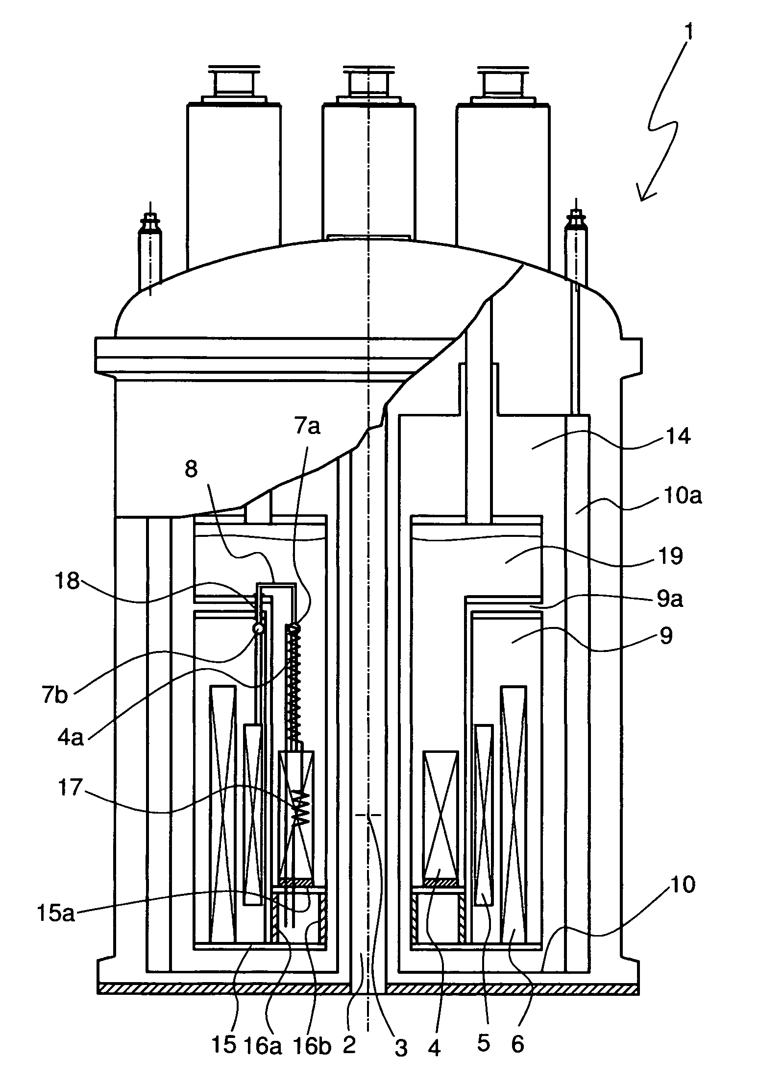
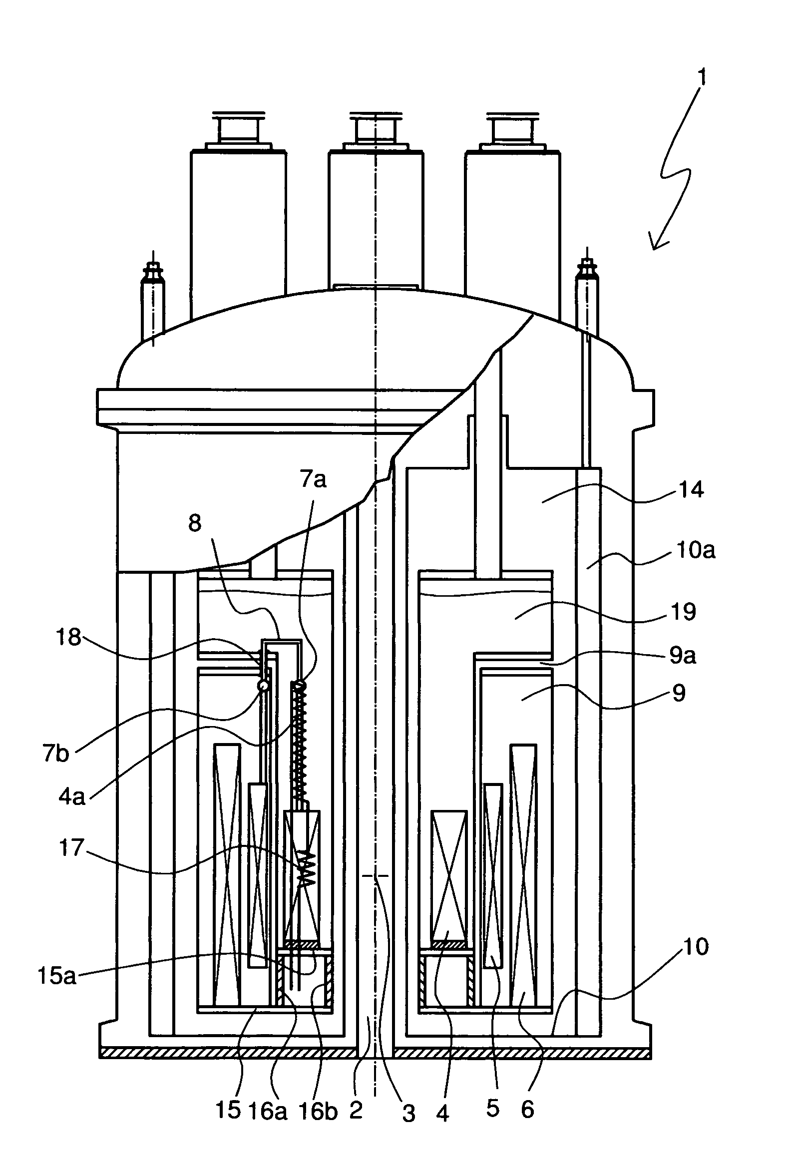
[0028]FIG. 1 shows an embodiment of a cryostat 1 in accordance with the invention. The cryostat 1 has a room temperature bore 2 in which a measuring volume 3 for a sample is provided. The measuring volume 3 is located in the center of a magnetic coil system, which is formed by three solenoid-shaped coil section 4, 5, 6. The radially innermost coil section 4 has a winding made from high temperature superconductor (HTS). The middle coil section 5 is wound with Nb3Sn wire and the outer most coil section 6 is wound with NbTi wire. The coil sections 5, 6 therefore represent low temperature superconductor (LTS) coil sections. The coil sections 4, 5, 6 are electrically connected to each other in series, as is shown in an exemplary fashion by means of superconducting joints 7a and 7b. At joint 7a, the high HTS material of a lead 4a is connected to a HTS coil section 4 by means of an adaptor section 8 made from NbTi. At joint 7b, the adaptor member 8 is connected to the Nb3Sn wire of the LTS...


PUM

PropertyMeasurementUnit
temperatureaaaaaaaaaa

Abstract

A cryostat (1) with a magnet coil system including superconductors for the production of a magnet field B0 in a measuring volume (3) has a plurality of radially nested solenoid-shaped coil sections (4, 5, 6) which are electrically connected in series, at least one of which being an LTS section (5, 6) with a conventional low temperature superconductor (LTS) and at least one of which being an HTS section (4) including a high temperature superconductor (HTS), wherein the LTS section (5, 6) is located in a first helium tank (9) of the cryostat (1) along with liquid helium at a helium temperature TL<4 K. The apparatus is characterized in that the HTS section (4) is disposed radially within the LTS section (5, 6) in a separate helium tank (19) of the cryostat (1) having normal liquid helium and is separated from the LTS section (5, 6) by means of at least one wall disposed between the two helium tanks. An HTS coil section can be maintained in the cryostat in accordance with the invention over a long period of time and in a reliable fashion.

Description

[0001]This application is the national stage of PCT / EP2007 / 001925 filed on Mar. 7, 2007 and also claims Paris Convention priority to DE 10 2006 012 511.8 filed Mar. 18, 2006.BACKGROUND OF THE INVENTION[0002]The invention concerns a cryostat having a magnetic coil system including superconducting materials for generation of a magnetic field B0 within a measurement volume, the magnet system having a plurality of radially nested solenoid-shaped coil sections connected in series at least one of which is an LTS section of a conventional low temperature superconductor (LTS) and with at least one HTS section of a high temperature superconductor (HTS), wherein the LTS portion is located in a helium tank of the cryostat having liquid helium at a helium temperature TL<4K.[0003]Cryostats of this kind are e.g. disclosed in DE 10 2004 007 340 A1.[0004]By way of example, nuclear magnetic resonance systems, in particular spectrometers, require very strong, homogenous and stable magnetic fields....

Claims


Application Information

Patent Timeline
Patent Type & Authority Patents(United States)
IPC IPC(8): H01F6/04H01F6/06G01V3/00
CPCH01F6/04
Inventor SCHNEIDER, THEOROTH, GERHARDKASTEN, ARNE
Owner BRUKER BIOSPIN
Why Eureka
Try Eureka