


Quick Research
Generate reliable direction feasibility study reports for your R&D in just a few steps.

Technical Q&A
Discover and master advanced knowledge NOW. Basics, ideas, possibilities, all at once.

Find Solutions
As an expert in R&D theories, this can generate solutions to your technical problems instantly.

Evaluate Feasibility
Analyze your overall solution with one click, know your potential R&D risks in advance.

Monitor Landscape
Get weekly tech updates, stay abreast of the latest tech innovations and key insights.
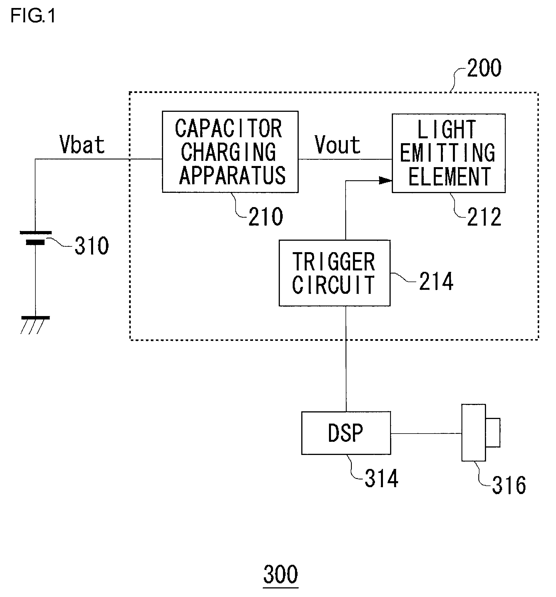
Capacitor charging apparatus
a technology of capacitors and charging apparatuses, which is applied in the direction of electric variable regulation, process and machine control, instruments, etc., can solve the problems of excessive power consumption, difficult to provide such a high-voltage resistor element within an lsi in the form of a built-in elemen
- Summary
- Abstract
- Description
- Claims
- Application Information
AI Technical Summary
Benefits of technology
Problems solved by technology
Method used
Image

Examples
first example configuration
[0069](First Example Configuration)
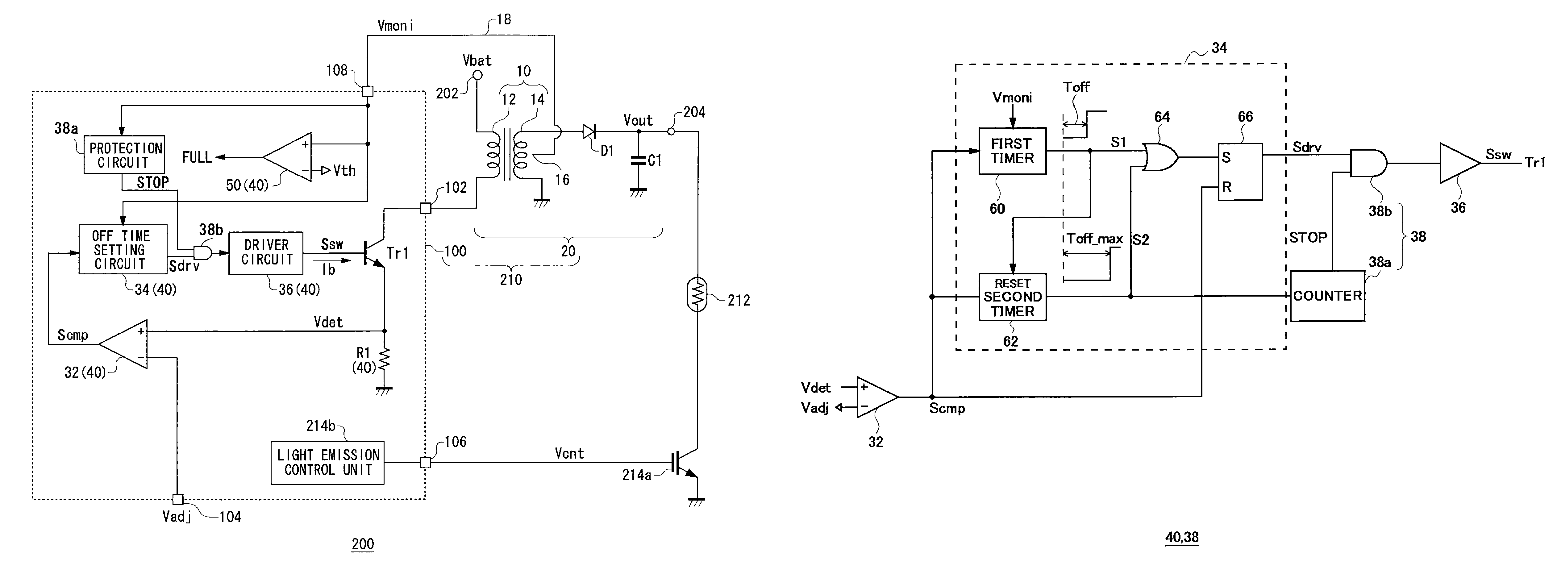
[0070]FIG. 3 is a block diagram which shows a first example configuration of the switching control unit 40 and the protection circuit 38.
[0071]The OFF time setting circuit 34 includes a first timer 60, a second timer 62, an OR gate 64, and an SR flip-flop 66.
[0072]The first timer 60 times the OFF period Toff which is set according to the monitoring voltage Vmoni. The first timer 60 receives the comparison signal Scmp from the comparator 32, and generates a first set signal S1 which is set to the high-level state (asserted) after the OFF period Toff elapses after the comparison signal Scmp has been asserted.
[0073]The second timer 62 and the OR gate 64 provide a function as a maximum OFF time setting circuit which limits the OFF period Toff to a predetermined maximum OFF period Toff_max or less.
[0074]When the comparison signal Scmp is asserted, the second timer 62 starts counting time, and generates a second set signal S2 which is set to the high-lev...
second embodiment
[0080](Second Embodiment)
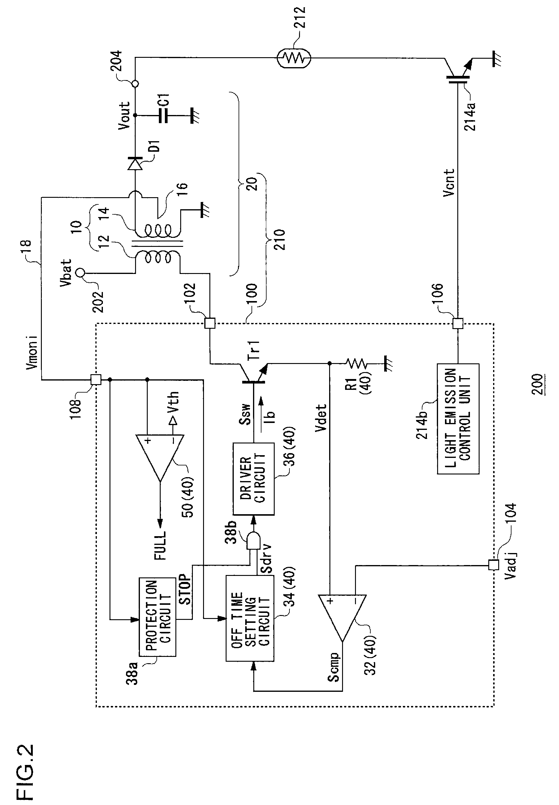
[0081]Description has been made in the first example configuration regarding an arrangement in which the circuit is protected by monitoring the OFF period Toff. Instead of such a method, in the second example configuration, detection is made whether or not an open-circuit state or a short-circuit state has occurred at the line 18 by comparing the monitoring voltage Vmoni with a threshold voltage. In this case, the protection circuit 38 comprises a comparator which compares the monitoring voltage Vmoni with a threshold voltage and a timer circuit which times a predetermined period of time according to the output signal of the comparator.
[0082]In a case in which the line 18 is in the open state or the grounded state, the monitoring voltage Vmoni is reduced down to the ground electric potential. Accordingly, such a circuit malfunction can be detected by comparing the monitoring voltage Vmoni with a low threshold voltage of around 0 V. Additionally, in a case in...
third embodiment
[0084](Third Embodiment)
[0085]The protection circuit 38 may monitor the impedance at the voltage monitoring terminal 108, instead of monitoring the monitoring voltage Vmoni. When the line 18 is connected to the tap 16 in the normal state, the impedance on the line 18 side measured via the voltage monitoring terminal 108 matches the impedance across the tap 16 provided to the secondary coil 14 and the ground terminal. In a case in which an open-circuit state or a short-circuit state has occurred at the line 18, the impedance changes. The protection circuit 38 may detect the change in the impedance.
[0086]The above is an example configuration of the protection circuit 38 and the switching control unit 40.
[0087]Returning to FIG. 2, the light emission control unit 214b generates a light emission control signal Vcnt so as to control the base voltage of the IGBT 214a connected to a light emission control terminal 106. When the light emission control signal Vcnt is switched to the high-leve...
PUM
 Abstract
Description
Claims
Application Information
 - R&D Engineer
- R&D Manager
- IP Professional
- Industry Leading Data Capabilities
- Powerful AI technology
- Patent DNA Extraction
Browse by: Latest US Patents, China's latest patents, Technical Efficacy Thesaurus, Application Domain, Technology Topic, Popular Technical Reports.
© 2024 PatSnap. All rights reserved.Legal|Privacy policy|Modern Slavery Act Transparency Statement|Sitemap|About US| Contact US: help@patsnap.com