
Ultra-sensitive detection of molecules on single molecule arrays

a single molecule array and ultra-sensitive technology, applied in the field of ultra-sensitive detection of analyte molecules or particles, can solve the problems of limiting the sensitivity of most detection techniques and the dynamic range, false positive signal generation, etc., and many known methods and techniques are further plagued by problems of non-specific binding

Active Publication Date: 2012-07-17
QUANTERIX CORP
View PDF176 Cites 71 Cited by
  • Summary
  • Abstract
  • Description
  • Claims
  • Application Information

AI Technical Summary

Benefits of technology

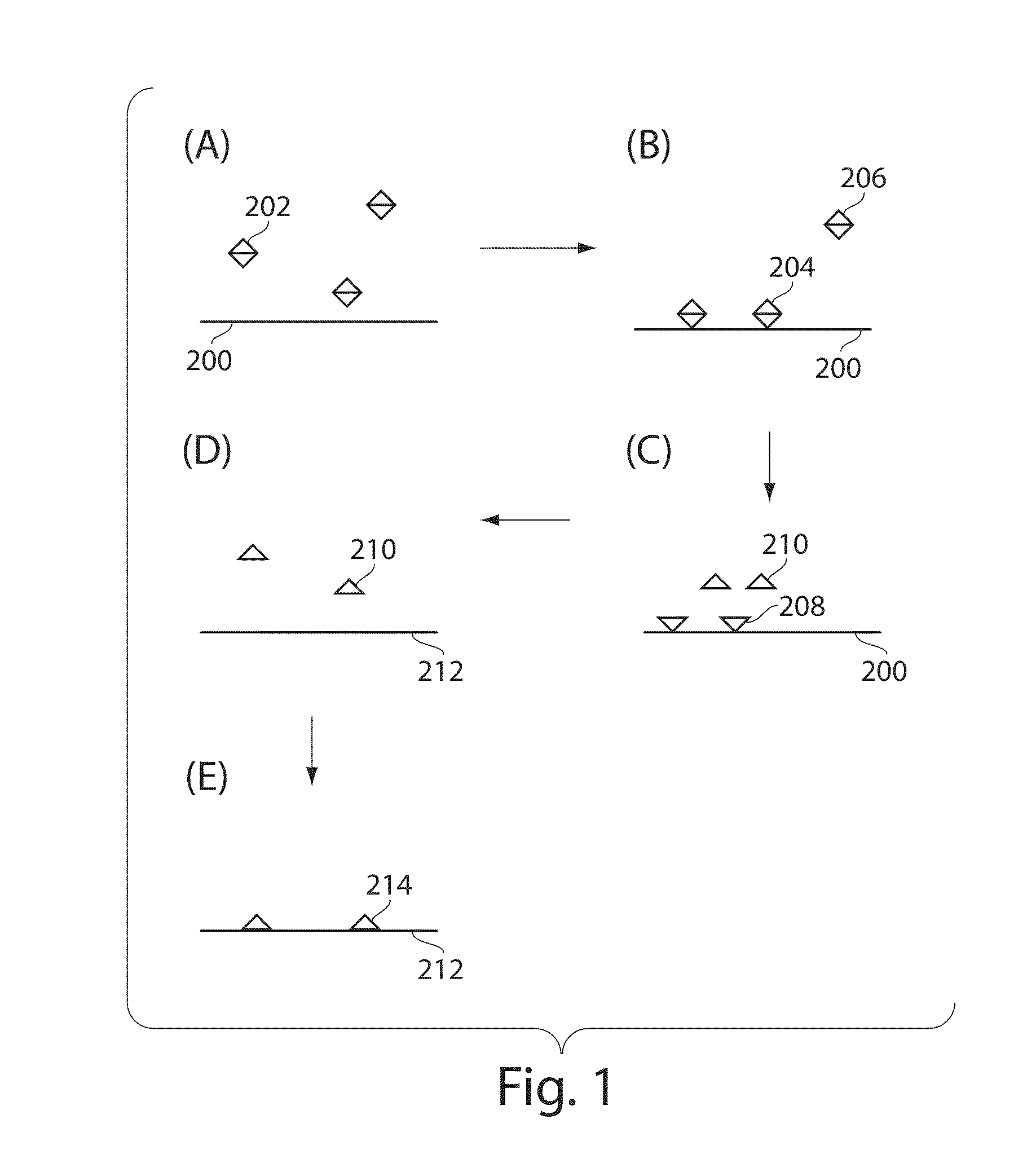
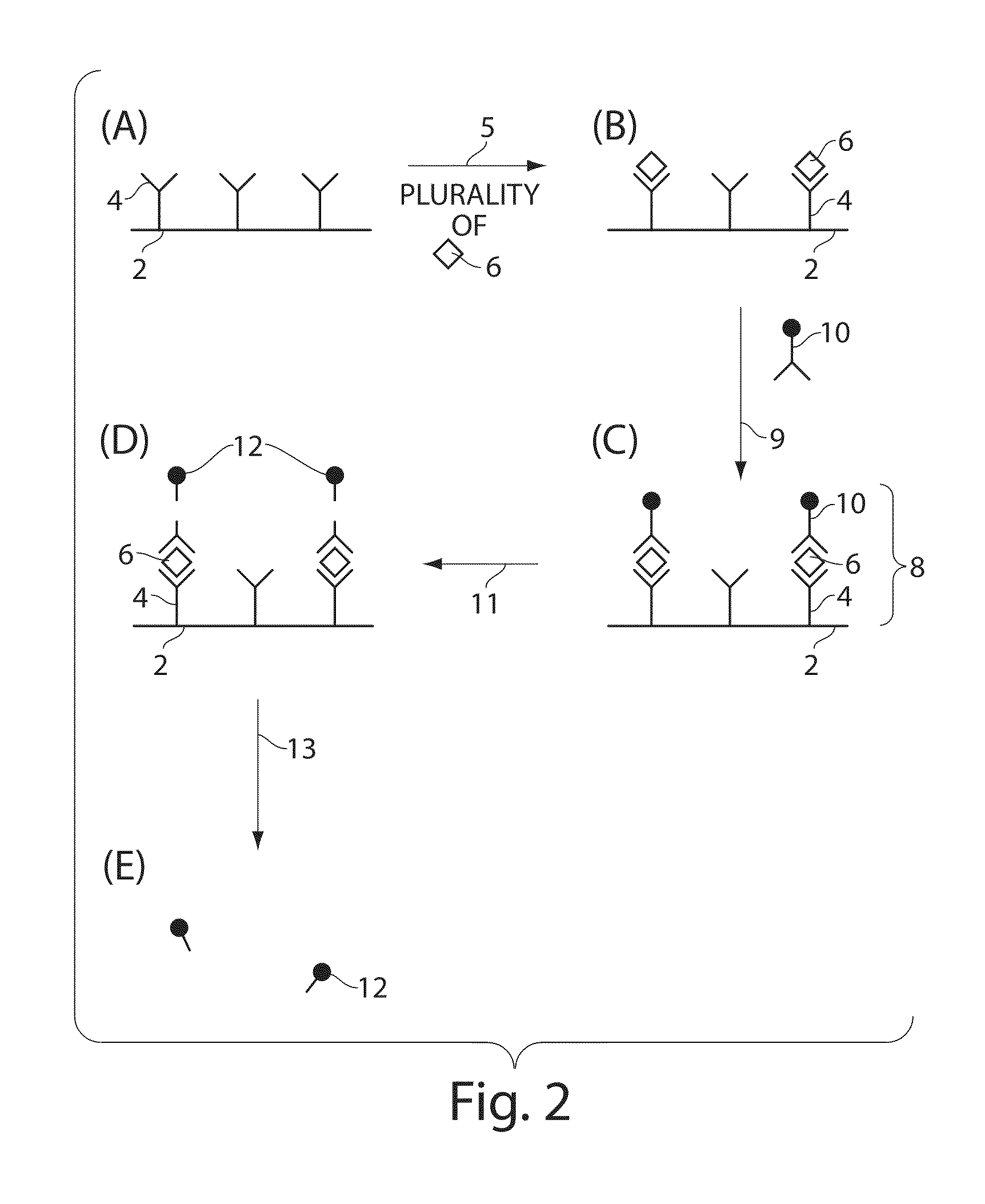
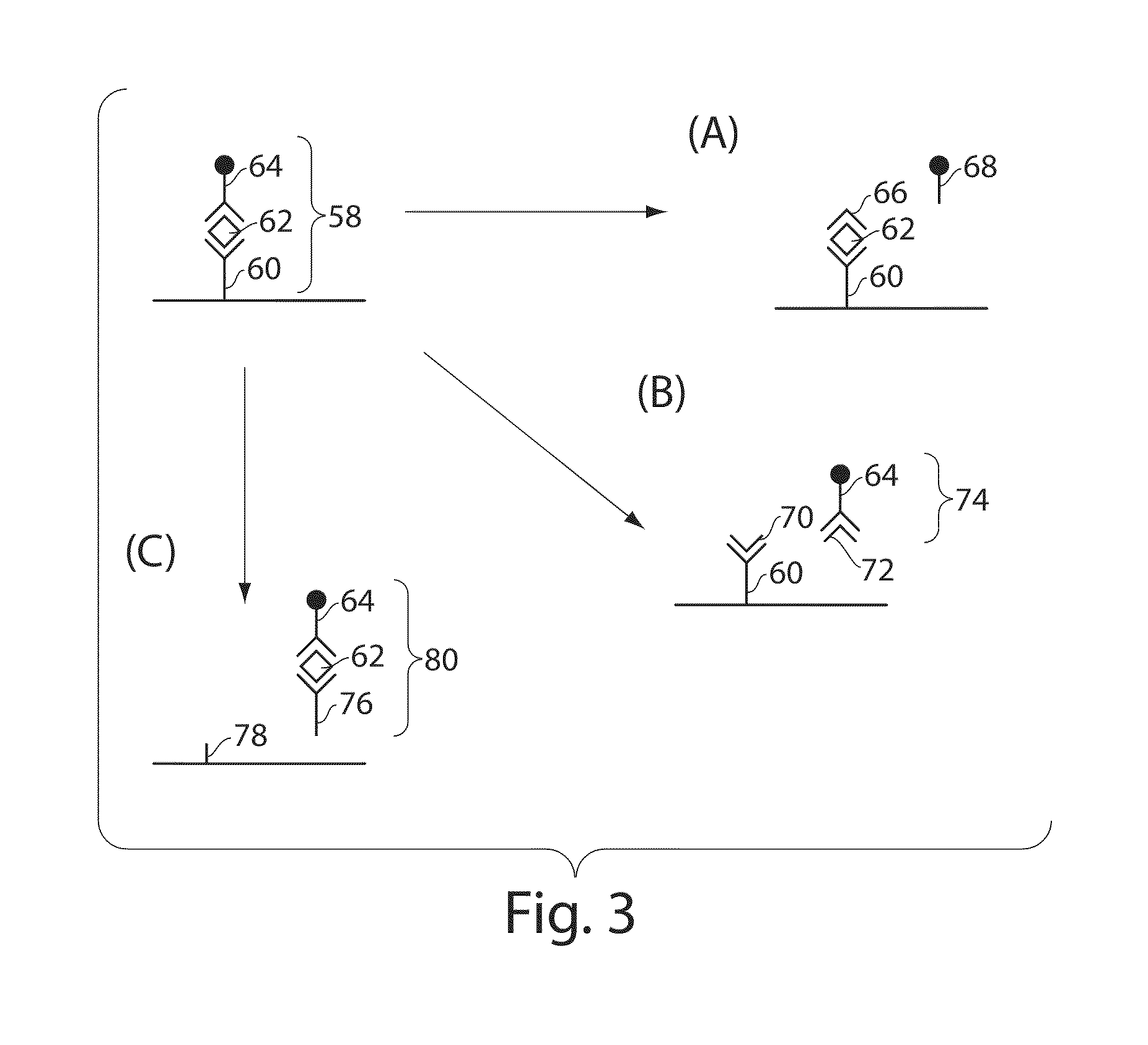
The present invention relates to a system and method for detecting analyte molecules or particles in a fluid sample. The system and method involve capturing the analyte molecules or particles on a substrate, releasing them from the substrate, and detecting them on or within a second substrate. The detection can be done by immobilizing the analyte molecules or particles on the substrate and then releasing them, or by exposing the second substrate to a precursor labeling agent and detecting the labeled molecules or particles. The invention can provide a measure of the concentration of the analyte molecules or particles in the fluid sample, with a high degree of accuracy.

Problems solved by technology

While the immuno-PCR method permits ultra low-level protein detection, it is a complex assay procedure, and can be prone to false-positive signal generation (see Niemeyer, C. M.; Adler, M.; Wacker, R.
One disadvantage of typical known methods and / or systems for accurately detecting and, optionally, quantifying low concentrations of a particular analyte in solution is that they are based on ensemble responses in which many analyte molecules give rise to the measured signal.
This disadvantage limits the sensitivity of most detection techniques and the dynamic range (i.e., the range of concentrations that can be detected).
Many of the known methods and techniques are further plagued with problems of non-specific binding, which is the binding of analyte molecules / particles to be detected or reporter species non-specifically to sites other than those expected.
This leads to an increase in the background signal, and therefore limits the lowest concentration that may be accurately or reproducibly detected.

Method used


Image

  • Ultra-sensitive detection of molecules on single molecule arrays
  • Ultra-sensitive detection of molecules on single molecule arrays
  • Ultra-sensitive detection of molecules on single molecule arrays

Examples


example 1

[0229]This example outlines the materials used in the following examples. Optical fiber bundles were purchased from Schott North America, Inc (Southbridge, Mass.). In this example, the core glass comprised barium, lanthanum, boron, silica, and aluminum. The refractive index of the core was 1.694, and the density was 4.23 g / cc. The cladding glass comprised silica, lead, potassium, sodium, and aluminum. The refractive index of the clading was 1.559, and the density was 3.04 g / cc. The fiber array was a bundle of 50,000 individual fibers, each with a core diameter of 4.5 μm and the center-to-center spacing of the cores was 8 μm.

[0230]Non-reinforced gloss silicone sheeting was obtained from Specialty Manufacturing Inc. (Saginaw, Mich.). Hydrochloric acid, 3-aminopropyl trimethoxysilane, anhydrous ethanol, molecular biology grade Tween®20, and N,N-Dimethyl formamide were all obtained from Sigma-Aldrich (Saint Louis, Mo.). Phosphate buffered saline, Blocker™ BSA (10%), Zeba Desalt spin col...

example 2

[0231]The example outlines the preparation of 1 um magnetic bead functionalized with TNF-alpha capture antibody. 20 uL of amine-reactive bead stock was washed three times in 0.1 M sodium borate coating buffer at pH 9.5 using a microtube magnetic separation device (BioMag® Tube Separator; Polysciences Inc., Warrington, Pa.). 500 ug TNF-alpha capture antibody was dissolved in 183.5 uL of sodium borate coating buffer. 104 uL of 3M ammonium sulfate was added to the antibody solution. 135 uL of the resulting antibody solution was added to the cleaned 20 uL bead aliquot and mixed at 37° C. for 24 hours. After incubation, the supernatant was removed using the magnetic separator, and 200 uL of PBS buffer containing 0.5% BSA and 0.05% Tween®20 was added to the beads. The beads were blocked overnight (˜8 hours) at 37° C. The functionalized and blocked beads were washed 3 times with 1 mL PBS buffer containing 0.1% BSA and 0.05% Tween®20. The beads were diluted to 1.5 mL in PBS containing 0.1% ...

example 3

[0232]The following is an example of the preparation of TNF-alpha detection antibody (binding ligand) comprising a disulfide cleavable biotin linkage. 100 ug of TNF-alpha detection antibody (R&D Systems, AF-210-NA) was dissolved in 100 uL PBS pH 7.4 buffer. 164 uL of PBS pH 7.4 buffer was added to a tared vial containing 1 mg sulfo-NHS-ss-biotin, yielding a 10 mM stock solution. 1.34 uL of the 10 mM stock solution was added to the 100 uL antibody solution, equating to a 20-fold molar excess of the biotin label. The antibody / NHS-ss-biotin solution was mixed for 1 hr at room temperature. The antibody-ss-biotin conjugate was purified using a Zeba Desalt Spin Column. The purification was performed according to the Pierce protocol for product #89882. The purified conjugate was diluted up to 2 mL, making a 50 ug / mL stock solution. 50 uL aliquots of this 50 ug / mL solution were stored at −20° C. for later use.


PUM

PropertyMeasurementUnit
volumeaaaaaaaaaa
volumeaaaaaaaaaa
volumeaaaaaaaaaa

Abstract

The present invention relates to systems and methods for detecting analyte molecules or particles in a fluid sample and in some cases, determining a measure of the concentration of the molecules or particles in the fluid sample. Methods of the present invention may comprise immobilizing a plurality of analyte molecules or particles to form a plurality of complexes, releasing at least a portion of some of the plurality of complexes, determining at least a portion of the plurality of complexes released, and determining a measure of the concentration of the analyte molecules or particles in a fluid sample.

Description

FIELD OF THE INVENTION[0001]The present invention relates to systems and methods for detecting analyte molecules or particles in a fluid sample and in some cases, determining a measure of the concentration of the molecules or particles in the fluid sample.BACKGROUND OF THE INVENTION[0002]Methods and systems that are able to quickly and accurately detect and, in certain cases, quantify a target analyte molecule or particle in a sample are the cornerstones of modern analytical measurements. Such systems and / or methods are employed in many areas such as academic and industrial research, environmental assessment, food safety, medical diagnosis, and detection of chemical, biological and / or radiological warfare agents. Advantageous features of such techniques may include specificity, speed, and sensitivity.[0003]Most current techniques for quantifying low levels of analyte molecules in a sample use amplification procedures to increase the number of reporter molecules in order to be able t...

Claims


Application Information

Patent Timeline
Patent Type & Authority Patents(United States)
IPC IPC(8): G01N33/543
CPCG01N33/54386C12Q1/6825G01N33/54326G01N33/54313Y10T436/143333
Inventor DUFFY, DAVID C.FERRELL, EVANRANDALL, JEFFREY D.RISSIN, DAVID M.WALT, DAVID R.
Owner QUANTERIX CORP
Learn More