
Microfabricated gas chromatograph

Active Publication Date: 2009-11-05
THE UNITED STATES OF AMERICA AS REPRESENTED BY THE SECRETARY OF THE NAVY
View PDF22 Cites 47 Cited by
  • Summary
  • Abstract
  • Description
  • Claims
  • Application Information

AI Technical Summary

Benefits of technology

[0010]The present invention has many advantages over the prior art to mitigate band broadening and tailing problems and to ensure all molecules of a single type experience about the same number of molecular interactions with the stationary phase for the same length of time. Allowing coating deposition before permanently joining two halves of the column enables the use of a variety of coating techniques that are not possible with conventional column coating techniques. Moreover, different segments (along the column) or halves (e.g., upper / lower) of a single column may be coated with different stationary phases without having to coat separate columns and join them together with the risk of adding additional “dead volume”. Different thicknesses of the polymer stationary phase may be coated along the column length for a gradated thickness. In particular, the thickness of the stationary phase may be particularly thick at the column entrance or be composed of a different sorbent material or mixture of sorbent materials. This can act to trap and focus analytes of interest prior to local heating of the column inlet to release them into the column length without any associated “dead volume” mixing problems associated with other injection techniques. Areas of the column that include geometrical discontinuity can be selectively excluded from the coating procedure. Additionally, designing one surface of the column with recessed grooves fosters local or advective mixing at these points and overcomes diffusion limited processes to promote transport across the column (i.e. perpendicular to the carrier gas flow) which accelerates the process to reach analyte distribution equilibrium between the carrier gas and the stationary phase. This reduces band broadening and tailing.

Problems solved by technology

Moreover, different segments (along the column) or halves (e.g., upper / lower) of a single column may be coated with different stationary phases without having to coat separate columns and join them together with the risk of adding additional “dead volume”.

Method used


Image

  • Microfabricated gas chromatograph
  • Microfabricated gas chromatograph
  • Microfabricated gas chromatograph

Examples


Embodiment Construction

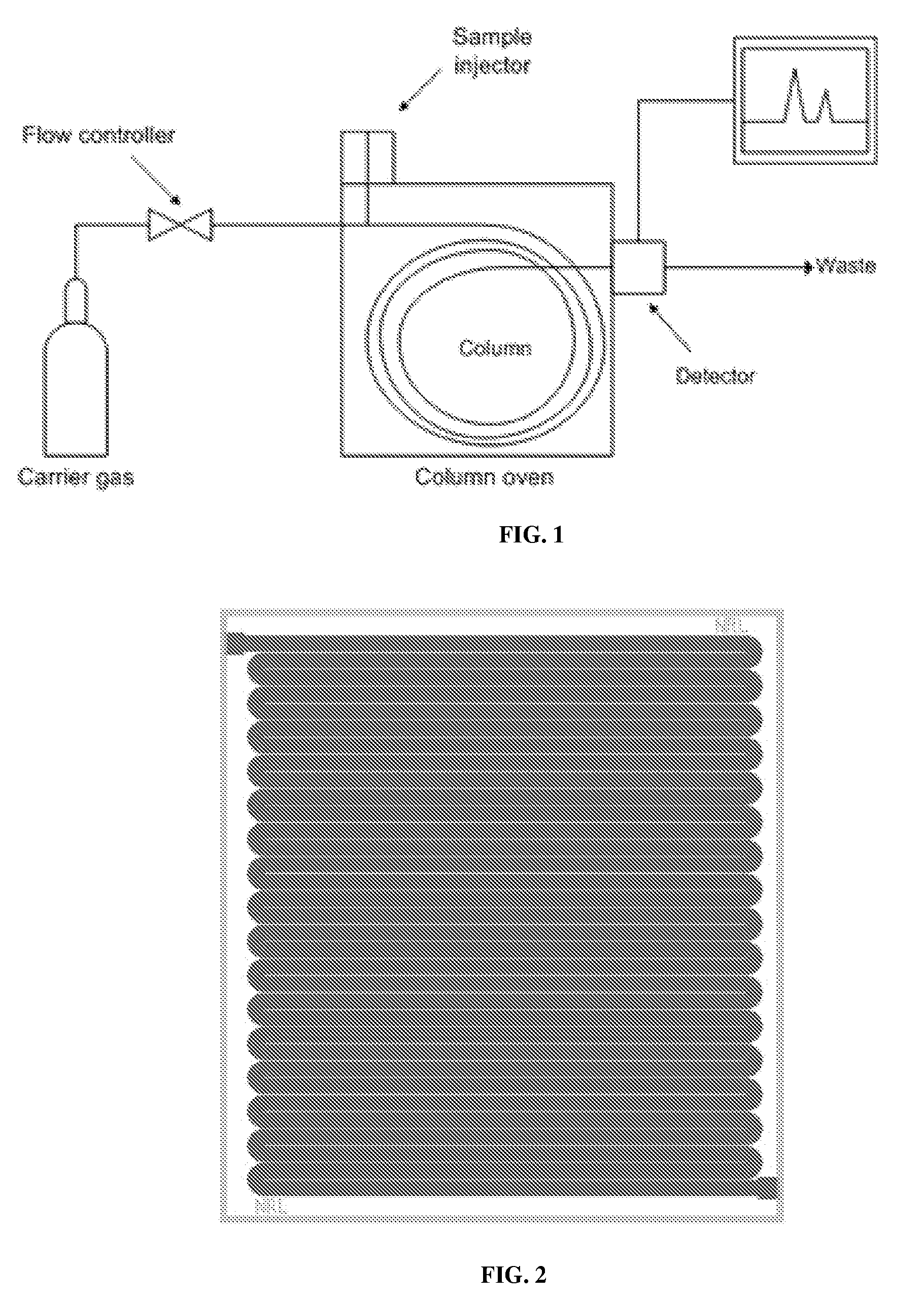
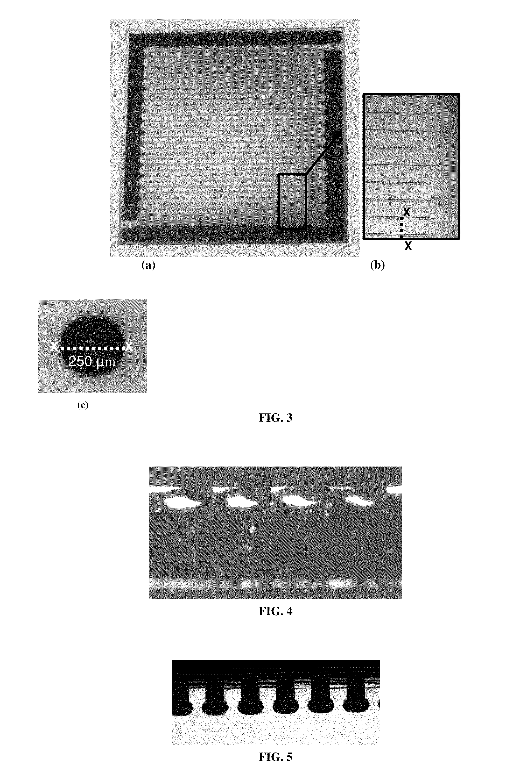
[0027]The present invention generally relates to microfabricated portable gas analyzers with high sensitivity and selectivity that may be used in applications such as chemical and biological agent detection, explosives detection, toxic industrial chemical detection, environmental monitoring, food and water screening, and medical diagnostics and treatment. A component of these analyzers is the gas chromatograph column which is used for separations of an injected mixture based on the relative sorption of the various analytes in the carrier gas by the stationary phase. One embodiment of the present invention is the design of the gas chromatograph column. A serpentine layout (and a modified serpentine layout) design with a circular cross-section has been simulated using computational fluid dynamic (CFD) modeling to help optimize chromatography performance. The column design comprises two halves: one half has a semi-circular cross-section while the other half can have a semi-circular cro...


PUM

PropertyMeasurementUnit
Temperatureaaaaaaaaaa
Thicknessaaaaaaaaaa
Acidityaaaaaaaaaa

Abstract

The present invention is generally directed to a microfabricated gas chromatograph column having two patterned substrates, each optionally having a stationary phase material coating, bonded together to provide a continuous flow channel. The flow channel can have a serpentine arrangement or a modified serpentine arrangement comprising alternating series of consecutive turns in one direction where each series has enough turns to move carrier gas and analyte molecules from the center of the column cross section to an outer wall of the channel or from one outer wall of the channel to the opposite outer wall. Different portions of the substrates can be coated with differing thicknesses of stationary phase material and / or with different stationary phase materials. The column can have a circular cross-section or a semi-circular cross-section where the flat portion of the cross-section has grooves. Also disclosed is the related method of making the microfabricated gas chromatograph column.

Description

PRIORITY CLAIM[0001]This Application claims priority from U.S. Provisional Application No. 61 / 071,489 filed on May 1, 2008 by R. Andrew McGill et al., entitled “MICROFABRICATED GAS CHROMATOGRAPH FOR TRACE ANALYSIS OF ILLICIT SUBSTANCES,” the entire contents of which are incorporated herein by reference.BACKGROUND OF THE INVENTION[0002]1. Field of the Invention[0003]The present invention relates generally to gas analyzers and, more specifically, to microfabricated gas chromatography for trace analysis.[0004]2. Description of the Prior Art[0005]Ever since its inception, the standard in volatile mixture separations for analysis has been gas chromatography (GC). Traditional GC involves injecting the analyte mixture into a tubular column which is coated with a stationary phase or packed with a relatively inert porous material that is itself coated with a stationary phase. A common configuration is a wall coated fused silica capillary column. Depending on the carrier gas flow conditions i...

Claims


Application Information

Patent Timeline
IPC IPC(8): B01D53/02B32B38/00
CPCB01J20/205B01J20/282B01J20/285B01J2220/54B01L3/502707G01N2030/025B01L2200/0689B01L2300/0816B01L2300/0883B01L2300/1827G01N30/6095B01L3/502746
Inventor MCGILL, R ANDREWPAI, REKHAMOTT, DAVID R.STEPNOWSKI, JENNIFER L.NGUYEN, VIET
Owner THE UNITED STATES OF AMERICA AS REPRESENTED BY THE SECRETARY OF THE NAVY
Learn More