Eureka AIR delivers breakthrough ideas for toughest innovation challenges, trusted by R&D personnel around the world.

Monolithic structures comprising polymeric fibers for chemical separation by liquid chromatography

a monolithic structure and polymeric fiber technology, applied in the direction of separation process, filtration separation, instruments, etc., can solve the problems of high backpressure and restrictive set of stationary phase chemistries, high capital costs associated with producing large volume columns, and high demands on system hydraulics (i.e. pumps)

Active Publication Date: 2006-02-16
CLEMSON UNIVERSITY
View PDF27 Cites 46 Cited by
  • Summary
  • Abstract
  • Description
  • Claims
  • Application Information

AI Technical Summary

Benefits of technology

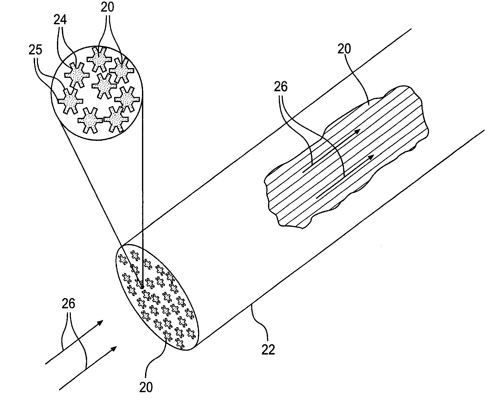
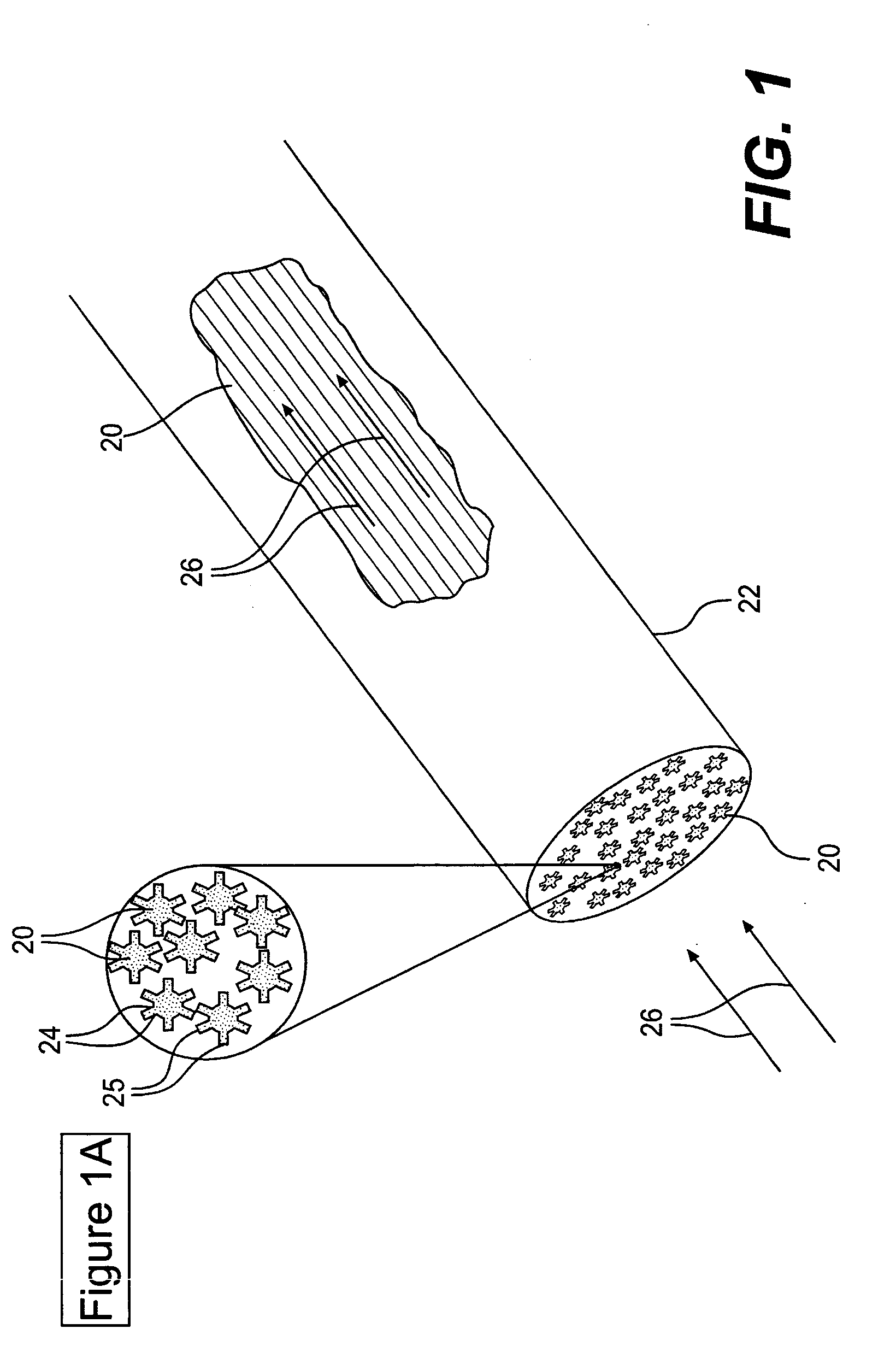
[0008] Optionally, the monolithic cartridge can include a wrap that surrounds the fibers of the cartridge that can be disposed along the axial length of the aligned fibers. In one particular embodiment, a wrap surrounding the fibers can exert suitable radial pressure upon the fibers so as to press the individual fibers together and form capillaries between adjacent fibers without the necessity of physically or chemically bonding the fibers together. In one particular embodiment, wherein a fluid can be forced through the cartridge under pressure, the monolithic cartridge can include a wrap surrounding the fibers that comprises a nonporous material.

Problems solved by technology

Here, the high backpressures and a limited set of stationary phase chemistries can be restrictive.
In the case of so-called “prep-scale” separations, the capital costs associated with producing large volume columns and the demands on the system hydraulics (i.e. pumps) are very high.

Method used


Image

  • Monolithic structures comprising polymeric fibers for chemical separation by liquid chromatography
  • Monolithic structures comprising polymeric fibers for chemical separation by liquid chromatography
  • Monolithic structures comprising polymeric fibers for chemical separation by liquid chromatography

Examples


example 1

[0080] Channeled propylene fibers having nominal diameters of approximately 50 μm and 8 branched channels running along their length were examined for protein separations. The channeled fibers were obtained from Eastman Chemical, Kingsport, Tenn. from a bobbin of fibers measuring more than 1000 meters in length.

[0081] Bundles of approximately 1200 fibers were loaded co-linearly into 4.6 mm i.d., 306 mm long stainless steel tubing (available from Valco Instruments, Houston, Tex.). Bundles were passed through the column such that the general alignment of the fibers within the column was longitudinally parallel such that broadening due to eddy diffusion, i.e., tortuous paths, was expected to be minimal.

[0082] The fiber lengths were trimmed to be flush with the tubing ends, and the column ends were sealed with 0.75 mm thick, 6.35 mm diameter frits including 10 μm pores and completed with column end fittings (available from Valco Instruments). Each fiber column had a packing mass of ab...

example 2

[0087] A monolithic cartridge of heat-bonded polyester fibers having substantially circular cross-sections was utilized to selectively separate solutions including the proteins ribonuclease A and cytochrome C. The solvent gradient was varied from 80:20 (water (0.1% TFA):acetonitrile(0.06% TFA)) to 70:30 over 10 minutes at a liquid volume flow rate of 1.75 mL / min. Systems and methods used for the separations were similar to those described in Example 1, above. Three separations of 20 μL injections were performed. Results of the separations are graphically illustrated in FIG. 12. As can be seen, the three injections yielded very reproducible separations.


PUM

PropertyMeasurementUnit
diametersaaaaaaaaaa
diameteraaaaaaaaaa
lengthaaaaaaaaaa

Abstract

Monolithic cartridges including a plurality of nominally aligned polymer fibers can be used as stationary phase materials for liquid chromatography separations. Bundles of fibers are packed together so as to form capillary channels between the fibers. Different polymer compositions permit the “chemical tuning” of the separation process. The fibers can be physically or chemically bonded at spaced locations throughout the cartridge or can be packed together under pressure by use of an encasing wrap to form the capillary channels. Use of fibers allows a wide range of liquid flow rates with very low backpressures. Applications in HPLC, cap-LC, prep-scale separations, analytical separations, waste remediation / immobilization, extraction of selected organic molecules / ions from solution, purification of liquid streams (process waste, drinking water, pure solvents), selective extraction of cell matter and bacteria from growth media, and immobilization of cell matter and bacteria are envisioned.

Description

BACKGROUND OF THE INVENTION [0001] The present invention relates to chemical analysis and cleansing of liquid streams and more particularly to liquid chromatography and wastewater treatment. [0002] At present, liquid-phase chemical separations are usually performed in “columns” prepared by the packing of metal tubes with spherical beads that are composed of either silica or polystyrene and have diameters of 3 to 50 μm. The more or less inert beads provide solid supports that are chemically modified to produce a surface having targeted chemical characteristics. For example, in performing reversed-phase liquid chromatography, long carbon chains (C-18) can be affixed to the surfaces of the beads so as to produce a hydrophobic surface for the separation of non-polar organics. In some systems, beads can include particular surface polymers upon formation, precluding the necessity of post-formation modification of the materials. [0003] Effective separations require dense packing of the bea...

Claims


Application Information

Patent Timeline
Patent Type & Authority Applications(United States)
IPC IPC(8): B01D11/04
CPCB01D15/08G01N2030/528B01J20/261B01J20/262B01J20/28014B01J20/28023B01J20/28042B01J20/28095B01J20/285B01J2220/54B01J2220/62B01J2220/82G01N30/6043G01N30/6078G01N30/6091B01D15/22
Inventor MARCUS, RICHARD KENNETHSTANELLE, RAYMAN DUPRE
Owner CLEMSON UNIVERSITY
Why Eureka
Eureka Blog
Learn More