Clamping element for fitting on a clamping tongue of a gripper as well as gripper fitted with such a clamping element

a technology of clamping element and clamping tongue, which is applied in the field of conveying technology, can solve the problems of clamping element falling off the arm laterally, affecting the service life of the clamping element, so as to achieve convenient exchange and reliable holding of objects.

Inactive Publication Date: 2012-07-17
FERAG AG
View PDF9 Cites 3 Cited by
  • Summary
  • Abstract
  • Description
  • Claims
  • Application Information

AI Technical Summary

Benefits of technology

[0010]The term clamping region means the region of the clamping elements in which in the case of application the clamping forces are mainly transmitted to the held object. By means of the two or more independent clamping regions, a clamping effect concentrated to different regions is realised. A dislocation of the product is thus impeded even if it comprises variations in thickness in the held regions. This can be supported by fitting the arms on the central clamping tongue part in a springing manner, which thus may additionally compensate thickness variations. The clamping regions differ from the rest of the regions of the carrier, e.g. by having an enlarged cross section (e.g. cushion-type swelling in the carrier) and / or by means of the elasticity module, in particular lower compliance in clamping direction. In the clamping region, preferably a certain elasticity / flexibility is provided in order to make the clamped force constant over the clamped area by means of adaptation to the form of the counter element or to the product and in particular to achieve a frontal area running in parallel to the product or the counter element respectively.
[0016]The invention has the advantage that the clamping elements, by means of the division of force onto two clamping regions enable a reliable holding of the objects by the gripper. They are easily exchangeable when worn or contaminated, however, are not displaced during operation or only to a low degree in relation to the clamping tongue.BRIEF DESCRIPTION OF THE DRAWINGS

Problems solved by technology

Clamping elements, which, as described in WO 2007 / 115421, are attached only by attaching them on the clamping tongues, have the disadvantage that they may come off the clamping tongues during operation, in particular in that the small displacements occurring during operation add up, such that the clamping element falls off the arm laterally.
A dislocation of the product is thus impeded even if it comprises variations in thickness in the held regions.

Method used


Image

  • Clamping element for fitting on a clamping tongue of a gripper as well as gripper fitted with such a clamping element
  • Clamping element for fitting on a clamping tongue of a gripper as well as gripper fitted with such a clamping element
  • Clamping element for fitting on a clamping tongue of a gripper as well as gripper fitted with such a clamping element

Examples


Embodiment Construction

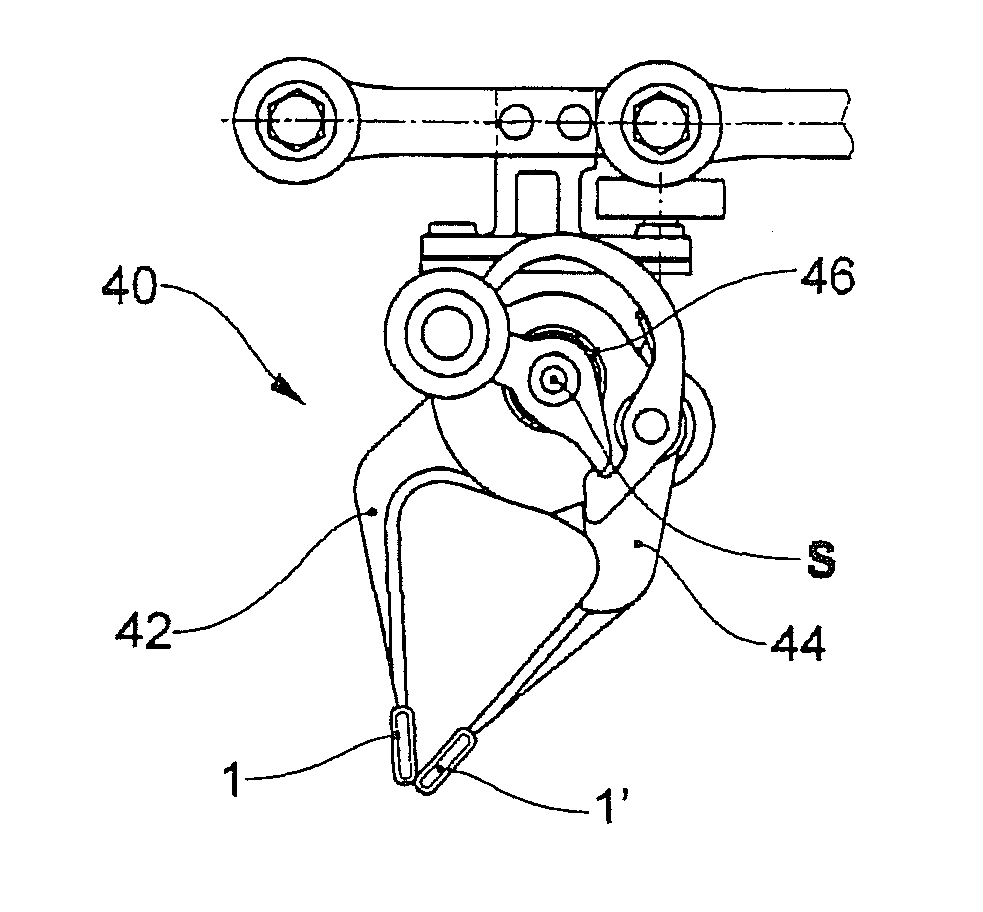
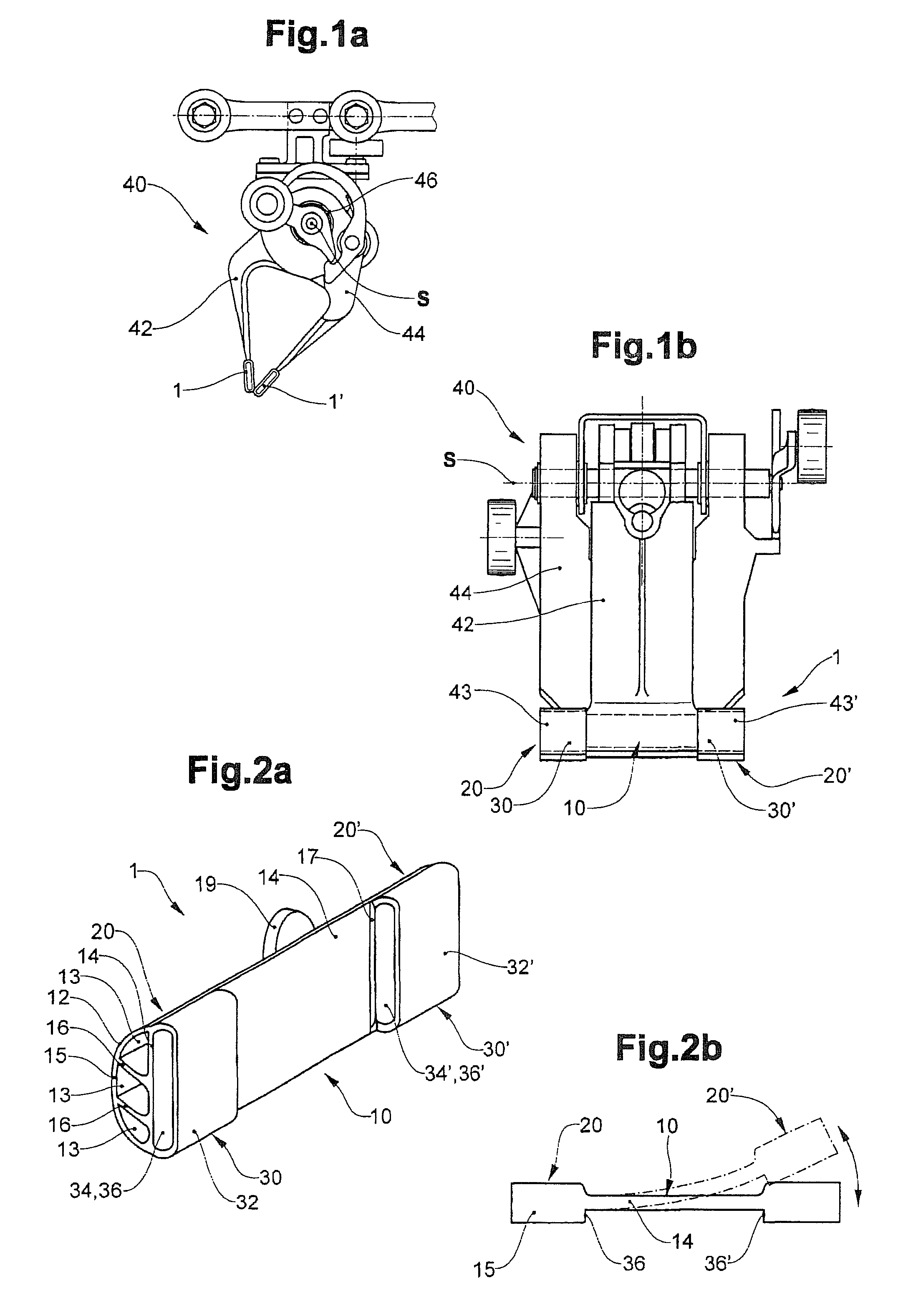
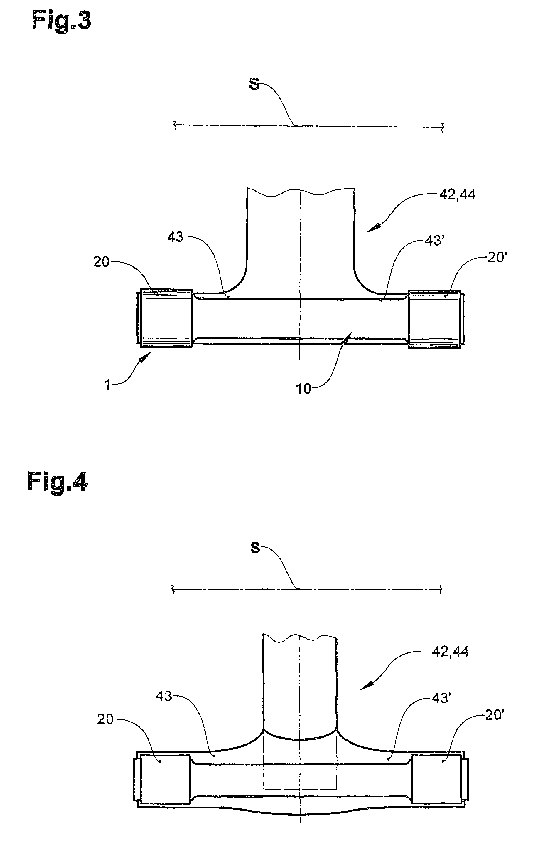
[0022]FIGS. 1a and b show a gripper 40 with two clamping tongues 42, 44, which are pivotable on a pivot axis S in relation to one another, in a view in the direction of the pivot axis (FIG. 1a) or in top view in perpendicular to it (FIG. 1b) respectively. With a means for creating a clamping force 46, e.g. a spring, the distal ends of the clamping tongues 42, 44 in closed condition of the gripper are pressed against each other or against the gripped product respectively. As shown in FIG. 1b, one of the clamping tongues 42 is designed in a T-shape and comprises laterally protruding arms 43, 43′. This kind of gripper is e.g. known from the publications DE-A310 2242 and WO 2007 / 115421 named at the outset and from EP-A 0 600 183, which is referenced here regarding the further construction and the mode of operation.

[0023]In order not to damage the product, to increase the extraction force in closed condition and to concentrate the clamping force to two regions, clamping elements 1, 1′ ar...


PUM


Abstract

A clamping element for attaching a gripper onto a clamping tongue as well as a gripper with this kind of clamping element is provided. The clamping element has a longitudinal carrier the width of which substantially corresponds to the width of the clamping tongue and at least two mutually distanced clamping regions. At least one fastening element for the detachable fastening of the clamping elements to the clamping tongue (42, 44) is provided. The clamping element provides an improved force division as well as a secure support on the clamping tongue.

Description

BACKGROUND OF THE INVENTION[0001]1. Field of the Invention[0002]The invention is in the field of conveying technology. It pertains to a clamping element for fitting onto a clamping tongue of a gripper as well as a gripper with this kind of clamping element.[0003]2. Description of Related Art[0004]The publication WO 2007 / 115421 describes a gripper comprising two clamping tongues as well as a means for generating a clamping force. The clamping tongues are pivotable in relation to one another on a pivot axis between two extreme positions, which corresponds to an open or closed configuration of the gripper respectively. At least one of the clamping tongues comprises, on its outer edge, two laterally protruding springing arms, i.e. protruding in parallel to the pivot axis. On these arms per clamping tongue two clamping elements are attached, in order to divide the clamping force between the two points or regions respectively and to make it uniform within these clamping regions.[0005]Clam...

Claims


Application Information

Patent Timeline
Patent Type & Authority Patents(United States)
IPC IPC(8): B66C1/44B25J15/00
CPCB65H29/003B65H2601/324B65H2405/571B65H2405/552
Inventor MAEDER, CARL CONRAD
Owner FERAG AG
Why Eureka
Try Eureka