Countermass weapon

a technology of counter-mass weapon and launching tube, which is applied in the direction of weapons, missile propulsion, firing/trigger mechanism, etc., can solve the problems of high production cost, achieve the effect of increasing the adaption of the weapon, facilitating the release and facilitating the release process of the launching tub

Active Publication Date: 2012-07-17
SAAB AB
View PDF13 Cites 6 Cited by
  • Summary
  • Abstract
  • Description
  • Claims
  • Application Information

AI Technical Summary

Benefits of technology

[0004]The object of the invention is to obtain a countermass weapon that is less complicated to manufacture reducing the costs and that at the same time avoids possible recoil problems for the gunner and making the weapon safer for the user.
[0005]The object of the invention is obtain by a countermass weapon characterized in that the countermass is designed such that a forward directed recoil is obtained and that the launching tube is designed to be disengageable from the firing and supporting unit during the forward directed recoil. By combining a forward directed recoil with a disengagement of the launching tube it is ensured that the gunner only feels a low level recoil. Most of the energy of the recoil is transferred as a kinetic energy to the launching tube. The combining of a forward directed recoil with a disengagement of the launching tube results in that the launching tube slips forward and due to that there is no risk of hurting the gunner or other persons behind the gunner. Furthermore, the safety of the weapon is increased due to the fact that the arming of the weapon can be dependent on the engagement or non-engagement of the firing and supporting unit to the launching tube.
[0006]According to a favourable development of the countermass weapon the countermass is provided with indications of fractions on the surface of the countermass to obtain a forward directed recoil. By providing indications of fractions in this way a forward directed recoil of suitable strength can be accurately defined.
[0012]Advantageously, it is proposed that the firing and supporting unit is designed re-usable for enabling connection to a plurality of different launchable units. This makes the weapon more flexible in that the same firing and supporting unit can be used together with a plurality of launching tubes brought by the gunner. These launching tubes can be of the same type but it is also possible to connect the firing and supporting unit to launching tubes containing different launchable units thus increasing the adaption of the weapon to different scenarios.
[0013]Furthermore it is proposed that the front piece is provided with a hook releasable from the launching tube by a movement backwards. This in combination with other releasable fastening means creates a reliable fastening of the firing and supporting unit to the launching tube and at the same time facilitates the releasing of the launching tube from the firing and supporting unit.
[0014]It is also proposed that the sight is provided with a holder designed to be folded at least partly around the launching tube. This solution also facilitates the releasing process of the launching tube from the firing and supporting unit in that the launching tube can glide within the holder.

Problems solved by technology

These circumstances taken together result in high production costs.

Method used


Image

  • Countermass weapon
  • Countermass weapon
  • Countermass weapon

Examples


Embodiment Construction

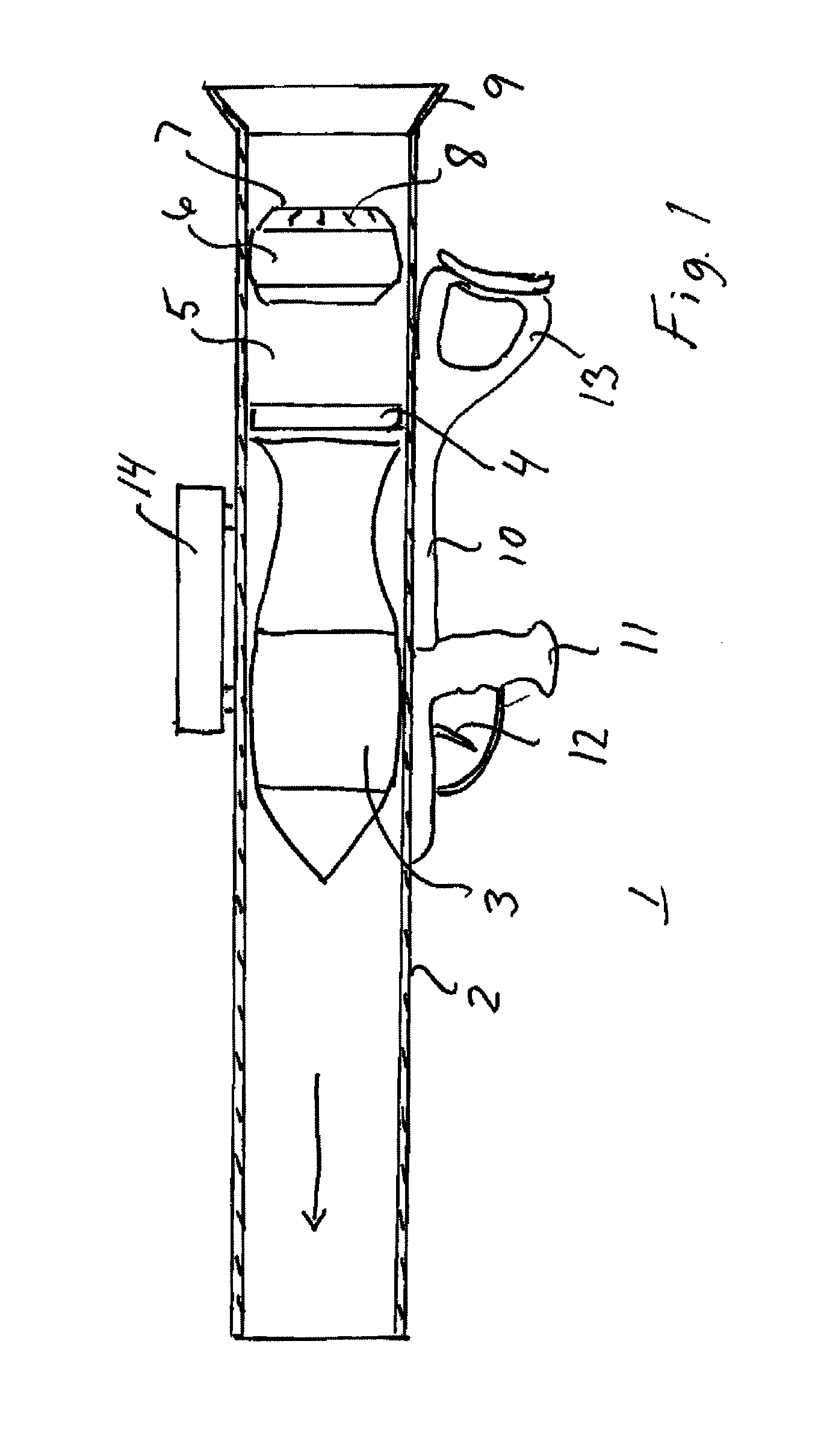
[0021]The countermass weapon 1 shown in FIG. 1 comprises an open launching tube 2 housing a launchable unit in the shape of a shell 3. Behind the shell 3 there is provided a propellant charge 4, a pressure chamber 5 and a countermass 6. The countermass 6 is provided with indications of fractions 7 on the surface 8 of the countermass 6 facing the rear end 9 of the launching tube 2.

[0022]The indication of fractions 7 are so designed that the desired forward acceleration of that launching tube is obtained. In order to open up the countermass 6 adequately parameters such as extension, number and position of the indications of fractions can considered. In this connection it can be referred to our U.S. Pat. No. 7,353,739 showing a countermass weapon having a countermass provided with indications of fractions.

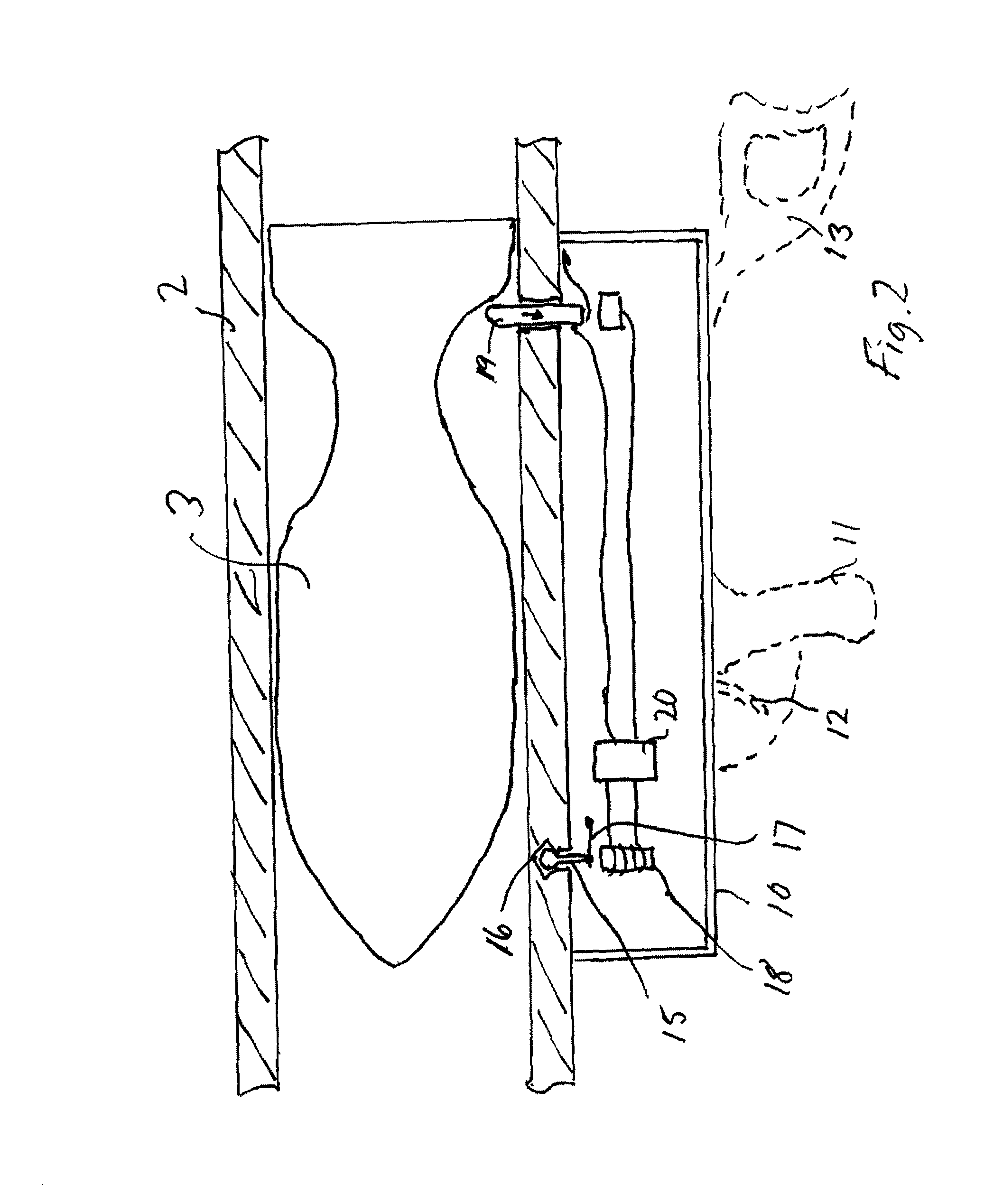
[0023]A releasable firing and supporting unit 10 is mounted on the launching tube 2 and comprises a handle 11 with a trigger 12, a shoulder piece 13 and a sight 14. In FIG. 2 it is ex...


PUM


Abstract

A countermass weapon including a launching tube open or openable in both ends. The launching tube houses a launchable unit, a countermass, a pressure chamber, a propellant charge that upon firing and combustion of the charge in cooperation with the pressure chamber and the countermass accelerates the launchable unit forwards in the tube at the same time as the countermass accelerates backwards in the tube, and a firing and supporting unit connected to the outside of the launching tube. The countermass is designed such that a forward directed recoil is obtained and the launching tube is designed to be disengageable from the firing and supporting unit during the forward directed recoil.

Description

CROSS-REFERENCE TO RELATED APPLICATIONS[0001]This application claims priority to European patent application 08445027.9 filed 4 Sep. 2008.FIELD OF THE INVENTION[0002]The present invention relates to a countermass weapon comprising a launching tube open or openable in both ends, the launching tube housing a launchable unit such as a rocket, a projectile, a shell or the like, a countermass, a pressure chamber, a propellant charge that upon firing and combustion of the charge in cooperation with the pressure chamber and the countermass accelerates the launchable unit forwards in the tube at the same time as the countermass accelerates backwards in the tube, and a firing and supporting unit connected to the outside of the launching tube.BACKGROUND OF THE INVENTION[0003]An example of a countermass weapon according to the above is previously known from EP patent 1 526 352. In countermass weapons of this type it is required that the recoil is on a low level. In order to keep the recoil on ...

Claims


Application Information

Patent Timeline
IPC IPC(8): F41A1/10
CPCF41A1/10F41F3/0455
Inventor JONSSON, RICHARD
Owner SAAB AB
Why Eureka
Try Eureka