
Manufacture of kinesiology tape

a technology of kinesiology tape and tape, which is applied in the field of manufacture of kinesiology tape, can solve the problems of difficult cutting of tape, difficult and inconvenient for many consumers, and more difficult for consumers to use in places

Active Publication Date: 2012-07-10
LUMOS
View PDF7 Cites 18 Cited by
  • Summary
  • Abstract
  • Description
  • Claims
  • Application Information

AI Technical Summary

Problems solved by technology

Nevertheless, there are a number of drawbacks in the current art regarding the manufacture and production of kinesiology tape.
However, the tape is often difficult to cut because of its elastic nature.
The tape must be cut with a very sharp object, such as sharp scissors, which makes it more difficult for consumers to use in places, such as a gym, where the consumer must carry the means to cut the tape with them.
This is difficult and inconvenient for many consumers who may forgo use of the tape and, therefore, miss its therapeutic and injury preventative uses.
Nevertheless, this suffers from a number of drawbacks.
Second, cutting individual strips while avoiding cutting the backing is difficult because the thickness of the tape may vary due to the elastic nature of the individual threads.
Third, perforations are difficult to achieve without making individual cuts to the interior of the tape.
Additional problems arise in the application of adhesive to the kinesiology tape.
Applying the adhesive in straight tracks makes the tape susceptible to forces pushing across the tracks.
Further, it is difficult to print on the kinesiology tape itself.
Therefore, if too much ink is applied to the tape, the printing will smudge and will bleed through the tape.
If too little ink is used, the printing will not be visible or the coloring will be wrong.
Accordingly, there are a number of disadvantages in the conventional manufacture of kinesiology tape that can be addressed.

Method used


Image

  • Manufacture of kinesiology tape
  • Manufacture of kinesiology tape
  • Manufacture of kinesiology tape

Examples


Embodiment Construction

[0009]This Summary is provided to introduce a selection of concepts in a simplified form that are further described below in the Detailed Description. This Summary is not intended to identify key features or essential characteristics of the claimed subject matter, nor is it intended to be used as an aid in determining the scope of the claimed subject matter.

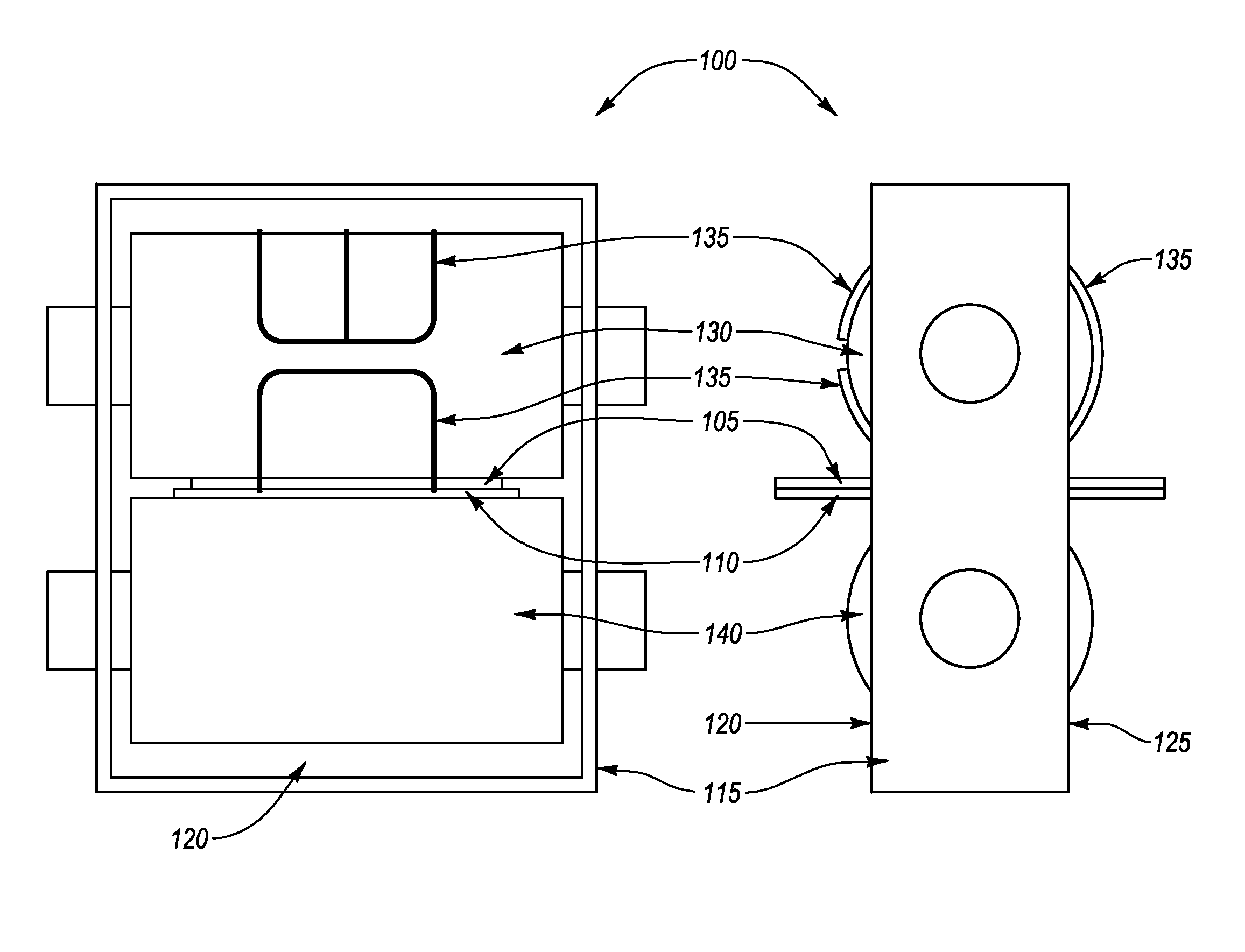
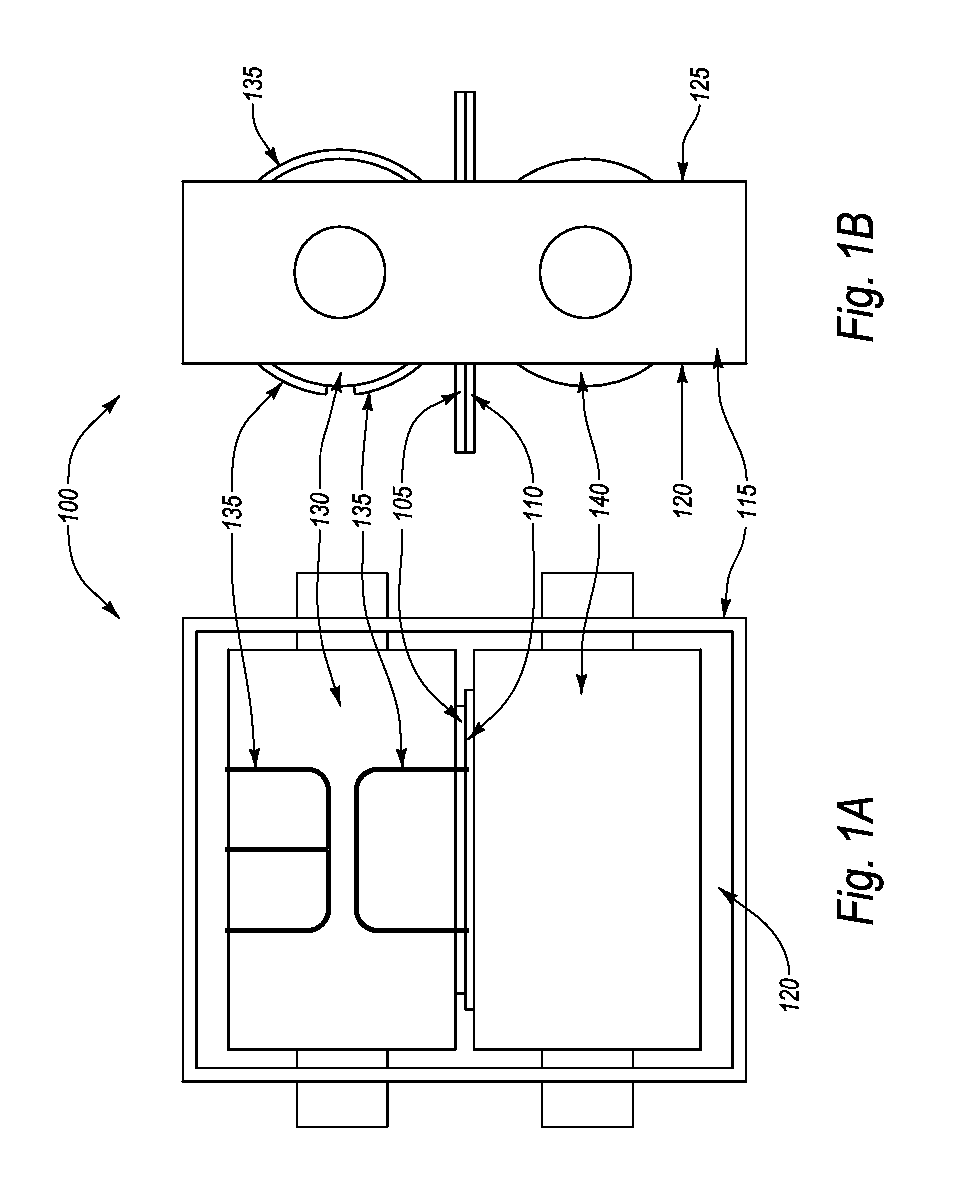
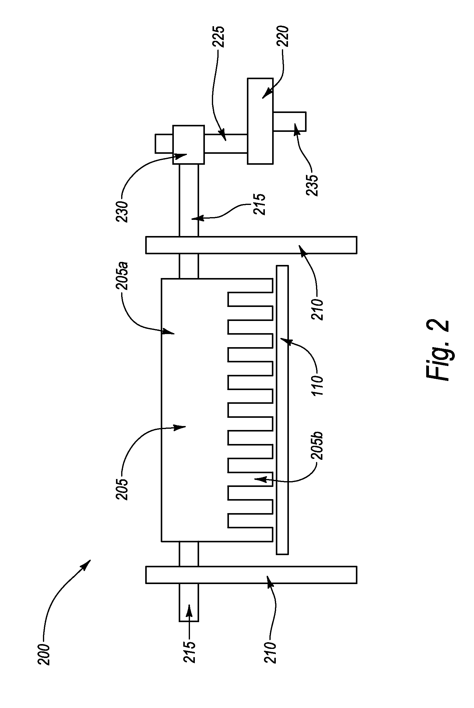
[0010]An embodiment of the invention includes a continuous feed variable depth die cut for use in cutting kinesiology tape. The die cut includes a housing, including a first opening configured to allow the kinesiology tape to enter the housing and a second opening configured to allow the kinesiology tape to exit the housing. The die cut also includes a roller inside the housing, wherein the roller is configured to rotate as the kinesiology tape passes over the roller and a die formed on the outer surface of the roller, wherein the die includes a cutting edge for cutting the kinesiology tape and wherein the cutting edge is formed ...


PUM

PropertyMeasurementUnit
widthaaaaaaaaaa
widthaaaaaaaaaa
circumferenceaaaaaaaaaa

Abstract

An embodiment of the invention includes a continuous feed variable depth die cut for use in cutting kinesiology tape. The die cut includes a housing, including a first opening configured to allow the kinesiology tape to enter the housing and a second opening configured to allow the kinesiology tape to exit the housing. The die cut also includes a roller inside the housing, wherein the roller is configured to rotate as the kinesiology tape passes over the roller and a die formed on the outer surface of the roller, wherein the die includes a cutting edge for cutting the kinesiology tape and wherein the cutting edge is formed in the shape of the strip of kinesiology tape to be cut. The die cut further includes a surface inside the housing, wherein the kinesiology tape passes over the surface when the kinesiology tape is being cut.

Description

CROSS-REFERENCE TO RELATED APPLICATIONS[0001]Not applicable.BACKGROUND OF THE INVENTION[0002]Kinesiology tape consists of a strip of elastic and non-elastic fibers, usually covered in cotton, which is placed on human skin. Kinesiology tape is useful in therapy to reduce soreness in overused and injured muscles and in rehabilitation to accelerate recovery. The tape can have a lifting effect on the skin which can reduce swelling and inflammation by improving circulation and reduce pain by taking pressure off pain receptors.[0003]Nevertheless, there are a number of drawbacks in the current art regarding the manufacture and production of kinesiology tape. In particular, kinesiology tape is generally sold in large rolls which the consumer must cut before using. However, the tape is often difficult to cut because of its elastic nature. The tape must be cut with a very sharp object, such as sharp scissors, which makes it more difficult for consumers to use in places, such as a gym, where t...

Claims


Application Information

Patent Timeline
Patent Type & Authority Patents(United States)
IPC IPC(8): B29C65/00B05C13/00B32B37/00B32B38/04B05D3/00B05C1/00B05C11/00
CPCA61F13/0283B26D3/08B26F1/384B65H35/0046Y10T156/1084Y10T156/14Y10T156/12Y10T156/1062Y10T156/1085Y10T83/4838
Inventor QUINN, REED M.
Owner LUMOS
Learn More