
Device and method for determining the dynamic elastic modulus of a material

a dynamic elastic modulus and material technology, applied in the direction of instruments, specific gravity measurement, and analysis of solids using sonic/ultrasonic/infrasonic waves, can solve the problems of inability to obtain true fundamental material properties without specific calibration, inability to monitor and inability to use tools for monitoring the complete time evolution of material properties. , to achieve the effect of short response time, easy, continuous, non-destructive and non-invasiv

Inactive Publication Date: 2012-07-10
SIKA TECH AG
View PDF15 Cites 2 Cited by
  • Summary
  • Abstract
  • Description
  • Claims
  • Application Information

AI Technical Summary

Benefits of technology

Enables continuous, non-destructive, and real-time monitoring of dynamic elastic modulus in materials, improving signal-to-noise ratio and portability, allowing for on-site measurement of materials with inclusions or porosity, and facilitating quality control of raw and final products.

Problems solved by technology

These tools, however, cannot be used for monitoring the complete time evolution of the chosen material properties.
In materials with air bubbles, porosity, cracks and / or inclusions that have a different ultrasonic response than the matrix, the material response can be more complex.
In particular, it is often not possible to obtain true fundamental material properties without specific calibration.
The main disadvantage of the known devices is that they can only be used over a narrow range of frequencies, whereas dynamic elastic properties of a material can strongly depend on the excitative frequency.
In addition, the devices known in the art are heavy and cumbersome, have high energy consumption and are therefore not suitable for easy on site measurement.
Furthermore, existing devices do not offer direct display of material properties and rely on data processing subsequently to the measurement which is time consuming.
Furthermore, existing devices have a high signal to noise ratio.

Method used


Image

  • Device and method for determining the dynamic elastic modulus of a material
  • Device and method for determining the dynamic elastic modulus of a material
  • Device and method for determining the dynamic elastic modulus of a material

Examples


Embodiment Construction

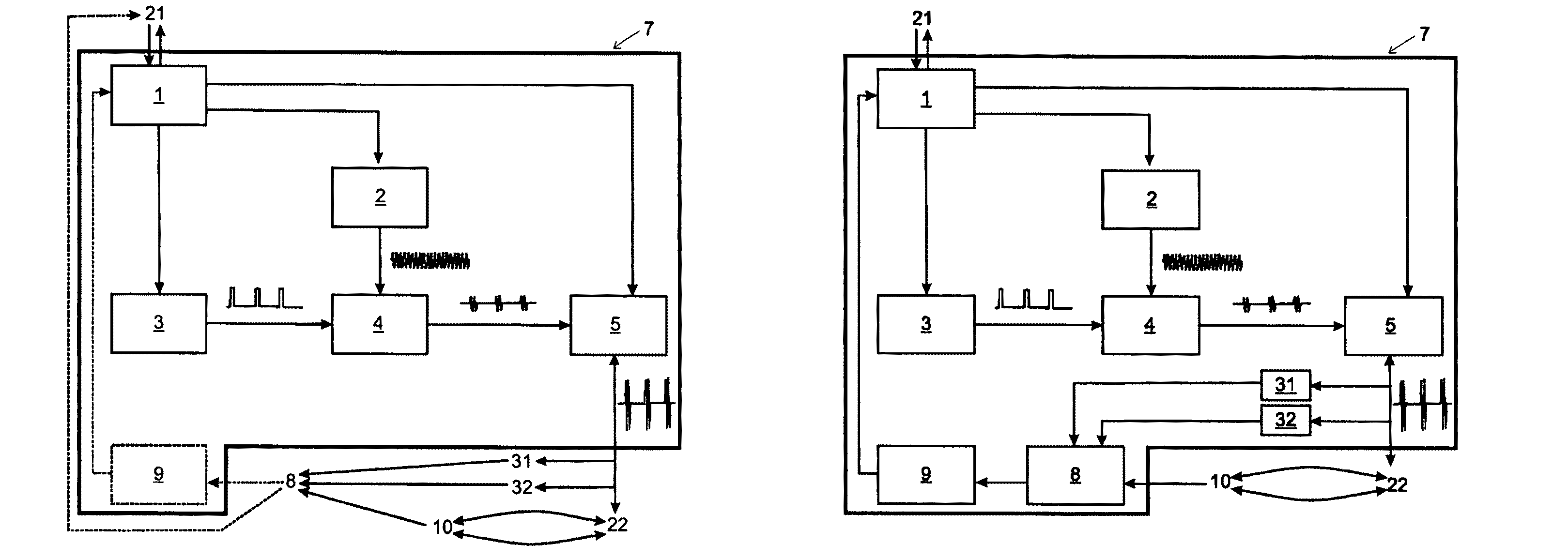
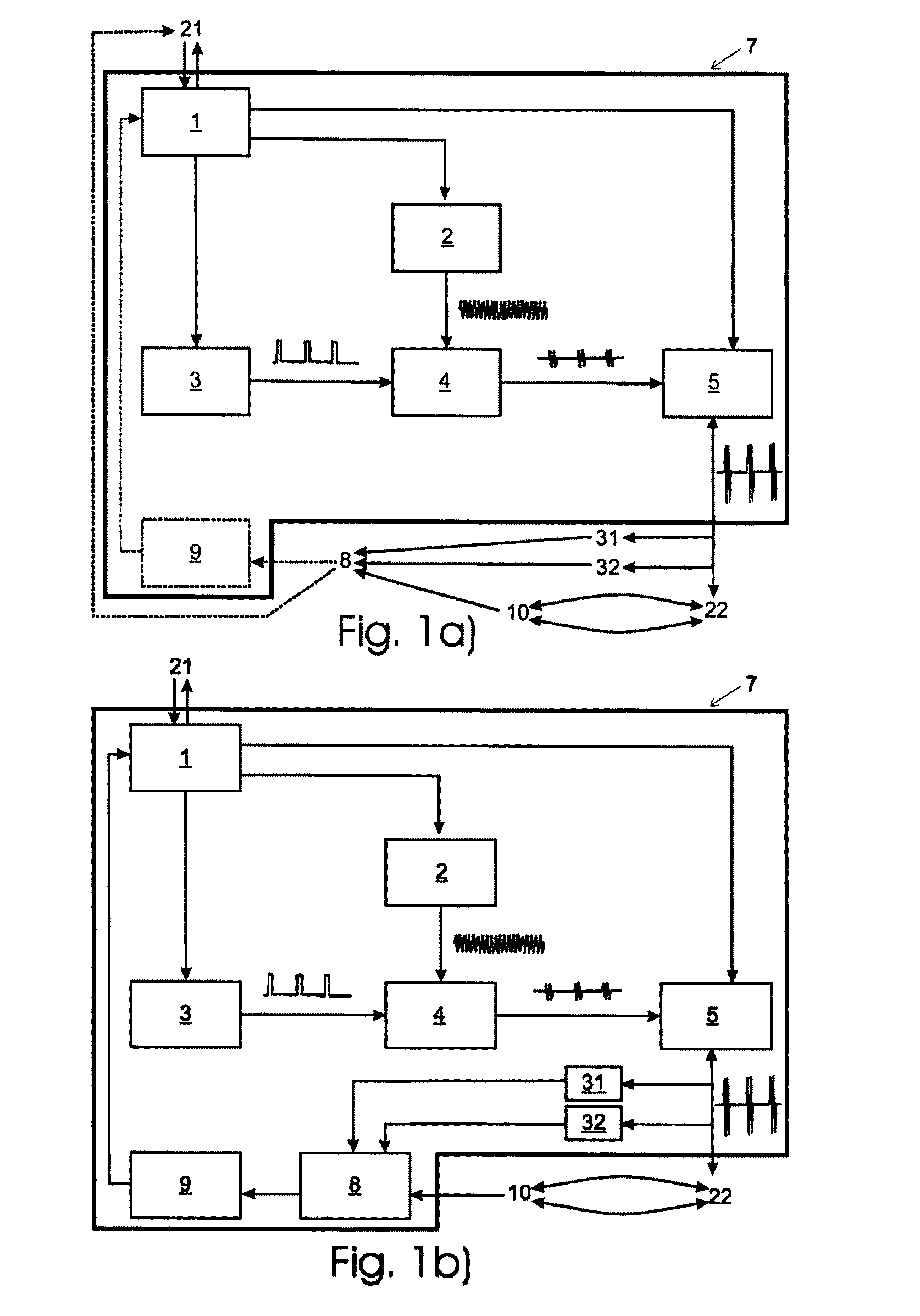
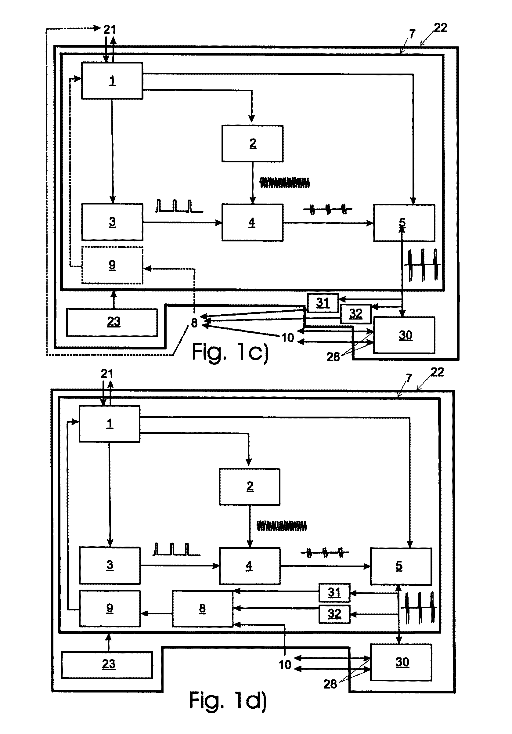
[0082]Referring now to the drawings, FIG. 1a shows a card 7 in connection with a multiplexer unit 22, a measuring device 10, and an analog to digital module 8, the card comprising a computer bridge interface 1 which sends a signal to a computer-readable medium 21, a low-voltage frequency-adjustable electronic oscillator 2, a signal generator 3, an electronic switch 4, a high voltage wide-band amplifier 5, and optionally an electronic memory 9. In addition, FIG. 1a shows the multiplexer unit 22, the measuring device 10, a tension limiter 31, a tension divider 32, the analog to digital module 8, and a computer-readable medium 21 which are separate from the card 7. The analog to digital module 8 is either a separate unit or part of a computer. The electronic memory 9 (shown in dashed lines) can either be on the card 7 or in the computer. In case that the analog to digital module 8 is part of a computer, preferably also the electronic memory 9 is part of a computer.

[0083]An acoustic sig...


PUM

PropertyMeasurementUnit
frequencyaaaaaaaaaa
power currentaaaaaaaaaa

Abstract

The invention relates to the determination of the dynamic elastic modulus of a material, such as a material comprising a mineral binder like cement, or gypsum, or the like, or a polymer, or ceramic, preferably mortar or concrete, in particular shotcrete, using sound, preferably ultrasound waves which penetrate the material and are continuously measured and analyzed. In particular, the invention relates to an apparatus, to a measuring device, and to a method for determining the dynamic elastic modulus of a material using the apparatus.

Description

TECHNICAL FIELD[0001]The invention relates to the determination of the dynamic elastic modulus of a material, such as a material comprising a polymer, or ceramic, or a mineral binder like cement or gypsum, or the like, in particular a material such as mortar, concrete, in particular shotcrete, using sound waves, preferably ultrasound waves, which penetrate the material and are continuously measured and analyzed. In particular, the invention relates to an apparatus, to a measuring device, and to a method for determining the dynamic elastic modulus of a material using the apparatus.BACKGROUND OF THE INVENTION[0002]Classical tools for measuring material properties of a material comprising mineral binders and polymers are for example the Vicat test, penetrometer, rheometer, needle penetration, or compression testing equipment like e.g. from Instron®. These tools, however, cannot be used for monitoring the complete time evolution of the chosen material properties.[0003]Ultrasonic analysi...

Claims


Application Information

Patent Timeline
Patent Type & Authority Patents(United States)
IPC IPC(8): G01N29/11
CPCG01N29/032G01N29/036G01N29/075G01N29/11G01N29/343G01N29/345G01N29/38G01N33/383G01N2203/0008G01N2203/0019G01N2203/0025G01N2203/0055G01N2203/0075G01N2203/0284G01N2291/011G01N2291/0235G01N2291/0251G01N2291/02827G01N2291/0422G01N2291/105
Inventor LOOTENS, DIDIERLOPEZ RIOS, JULIENFLATT, ROBERTBLANK, NORMAN
Owner SIKA TECH AG
Learn More