
Remote vacuum or pressure sealing device and method for critical isolated systems

a vacuum or pressure sealing and remote technology, applied in the direction of cables, manufacturing tools, nuclear engineering, etc., can solve the problems of exposing technicians to great risks, requiring a lot of care, and inserting the target material is a dangerous task

Inactive Publication Date: 2012-07-10
JEFFERSON SCI ASSOCS LLC
View PDF26 Cites 5 Cited by
  • Summary
  • Abstract
  • Description
  • Claims
  • Application Information

AI Technical Summary

Benefits of technology

The present invention is a remote vacuum or pressure sealing apparatus and method for sealing a critical isolated system. The apparatus includes a fixed threaded sealing surface on the isolated system, a gasket, and an insert consisting of a plug with a protruding sample holder. The apparatus also includes an insert coupling device for inserting samples within the isolated system, which includes a threaded fastener for cooperating with the fixed threaded sealing surface on the isolated system. The apparatus also includes an insertion tool for maintaining the orientation of the insert and limiting exposure of the user to the isolated system as the seal is made vacuum or pressure tight. The sealing method utilizes bearings constructed of a metal dissimilar to that of the isolated system, which enables the pressure on the sealed system to increase as the temperature decreases. The sealing apparatus maintains a pressure or vacuum tight seal throughout a wide temperature range including 300K-35 mK. The remote aspect of the sealing apparatus maintains the isolation of the system from the user's environment, safely preserving the user and the system from detrimental effect from each respectively. The technical effects of the invention include reducing potential danger to personnel, minimizing the effect of the environment on the isolated system, and maintaining the orientation of the sealing surface with respect to the mating surface.

Problems solved by technology

As a result of the radiation exposure, inserting the target material is a dangerous task that requires much care on the part of technicians and exposes them to great risk.

Method used


Image

  • Remote vacuum or pressure sealing device and method for critical isolated systems
  • Remote vacuum or pressure sealing device and method for critical isolated systems
  • Remote vacuum or pressure sealing device and method for critical isolated systems

Examples


Embodiment Construction

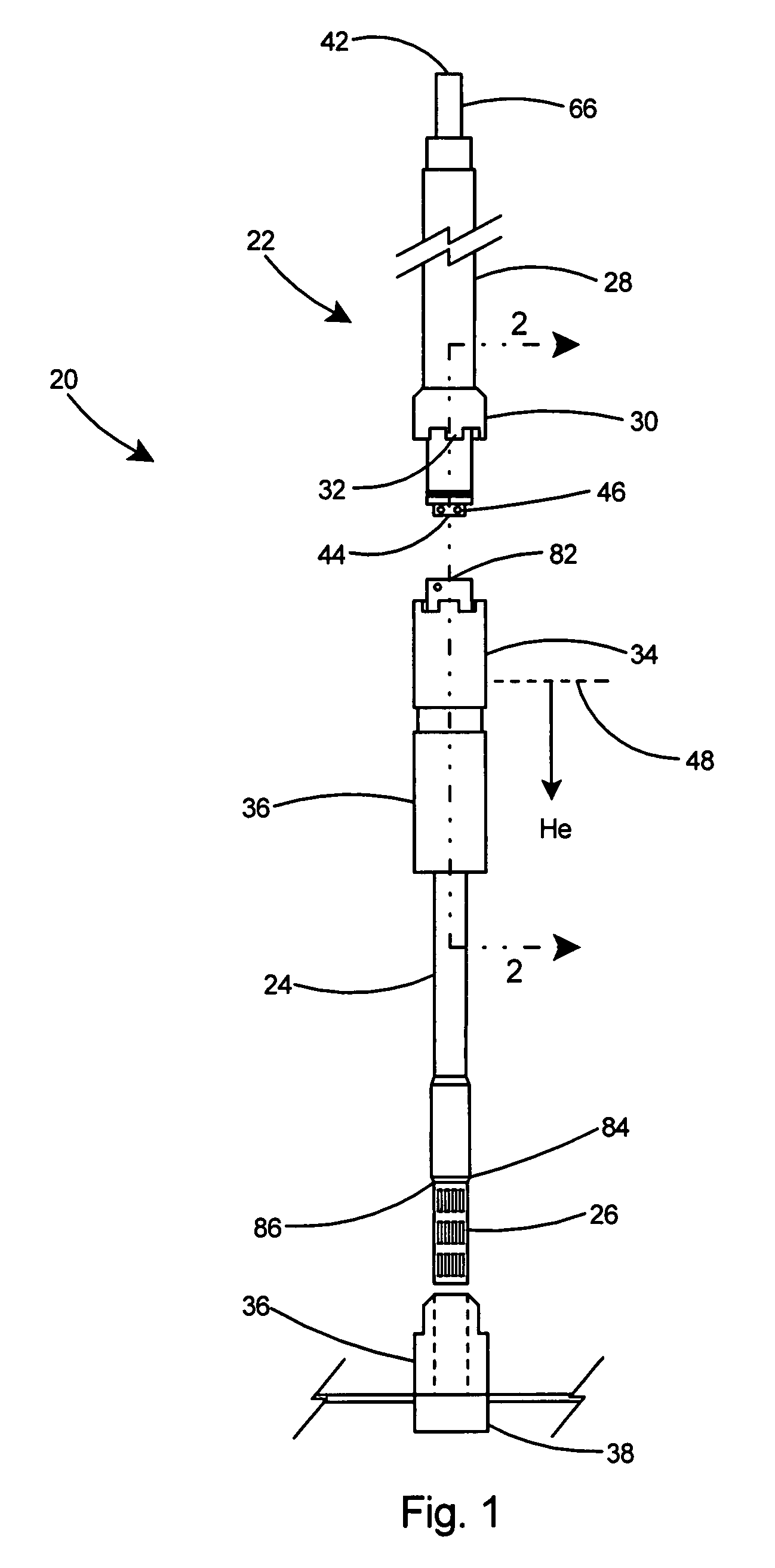
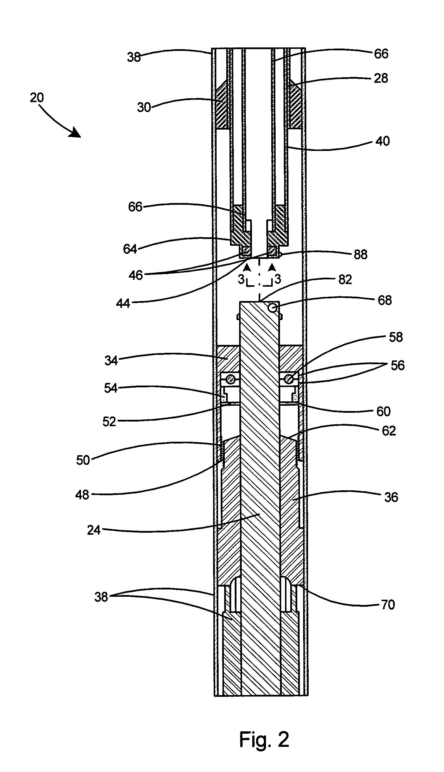
[0022]With reference to FIG. 1, the present invention comprises a remote vacuum or pressure sealing system for critical isolated systems. Although the remote sealing device of the present invention has utility for sealing isolated systems under both vacuum and pressure, hereinafter the description of the invention will be in terms of a vacuum sealing system.

[0023]As shown in FIG. 1, a preferred embodiment of the remote sealing system 20 includes an elongated tubular insertion and coupling tool 22 and a tubular target stick 24 with a target cup 26. The insertion and coupling tool 22 includes an outer wrench shaft 28 and a toothed coaxial socket wrench 30 integral with the lower portion of the outer wrench shaft 28. The socket wrench 30 includes one or more teeth 32 for engaging an internally threaded fastener 34 that will be threaded upon an externally threaded mounted fixed seal 36 that forms a portion of an isolated system 38. The isolated system 38 is typically maintained at a vac...


PUM

PropertyMeasurementUnit
temperatureaaaaaaaaaa
thicknessaaaaaaaaaa
thicknessaaaaaaaaaa

Abstract

A remote vacuum or pressure sealing apparatus and method for making a radiation tolerant, remotely prepared seal that maintains a vacuum or pressure tight seal throughout a wide temperature range. The remote sealing apparatus includes a fixed threaded sealing surface on an isolated system, a gasket, and an insert consisting of a plug with a protruding sample holder. An insert coupling device, provided for inserting samples within the isolated system, includes a threaded fastener for cooperating with the fixed threaded sealing surface on the isolated system. The insert coupling device includes a locating pin for azimuthal orientation, coupling pins, a tooted coaxial socket wrench, and an insert coupling actuator for actuating the coupling pins. The remote aspect of the sealing apparatus maintains the isolation of the system from the user's environment, safely preserving the user and the system from detrimental effect from each respectively.

Description

[0001]The United States of America may have certain rights to this invention under Management and Operating contract No. DE-AC05-06OR23177 from the Department of Energy.FIELD OF THE INVENTION[0002]This invention relates to achieving a vacuum or pressure tight seal on an isolated system and more particularly to a device and method for making a radiation tolerant, remotely prepared seal that maintains a vacuum or pressure tight seal.BACKGROUND OF THE INVENTION[0003]In particle accelerators, nuclear power plants, chemical plants and the like, it is sometimes necessary to introduce a material into a hazardous or controlled environment remotely to insure the protection of personnel from the hazardous environment. A controlled environment could include sealed areas that are under vacuum or pressure or which contain hazardous materials such as chemicals or radioactive substances.[0004]At the Jefferson National Lab, for example, in the electron beam line, the electron beam is typically main...

Claims


Application Information

Patent Timeline
Patent Type & Authority Patents(United States)
IPC IPC(8): B23P19/04B25B27/14H02G1/08B65H59/00E21C29/16
CPCB01J3/03H05H7/00G21F7/06Y10T29/53843Y10T29/53943Y10T29/53883Y10T29/53913
Inventor BROCK, JAMES DAVIDKEITH, CHRISTOPHER D.
Owner JEFFERSON SCI ASSOCS LLC
Learn More