Sound source separation system, sound source separation method, and acoustic signal acquisition device
a separation system and sound source technology, applied in the direction of transducer casings/cabinets/supports, electrical transducers, instruments, etc., can solve the problems of difficult to hear, unnatural force on users to use close-talking type microphones,
- Summary
- Abstract
- Description
- Claims
- Application Information
AI Technical Summary
Benefits of technology
Problems solved by technology
Method used
Image
Examples
first embodiment
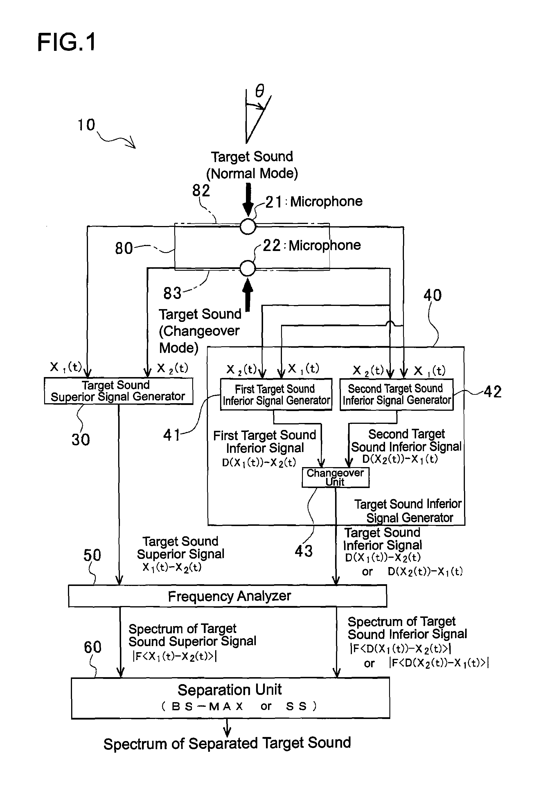
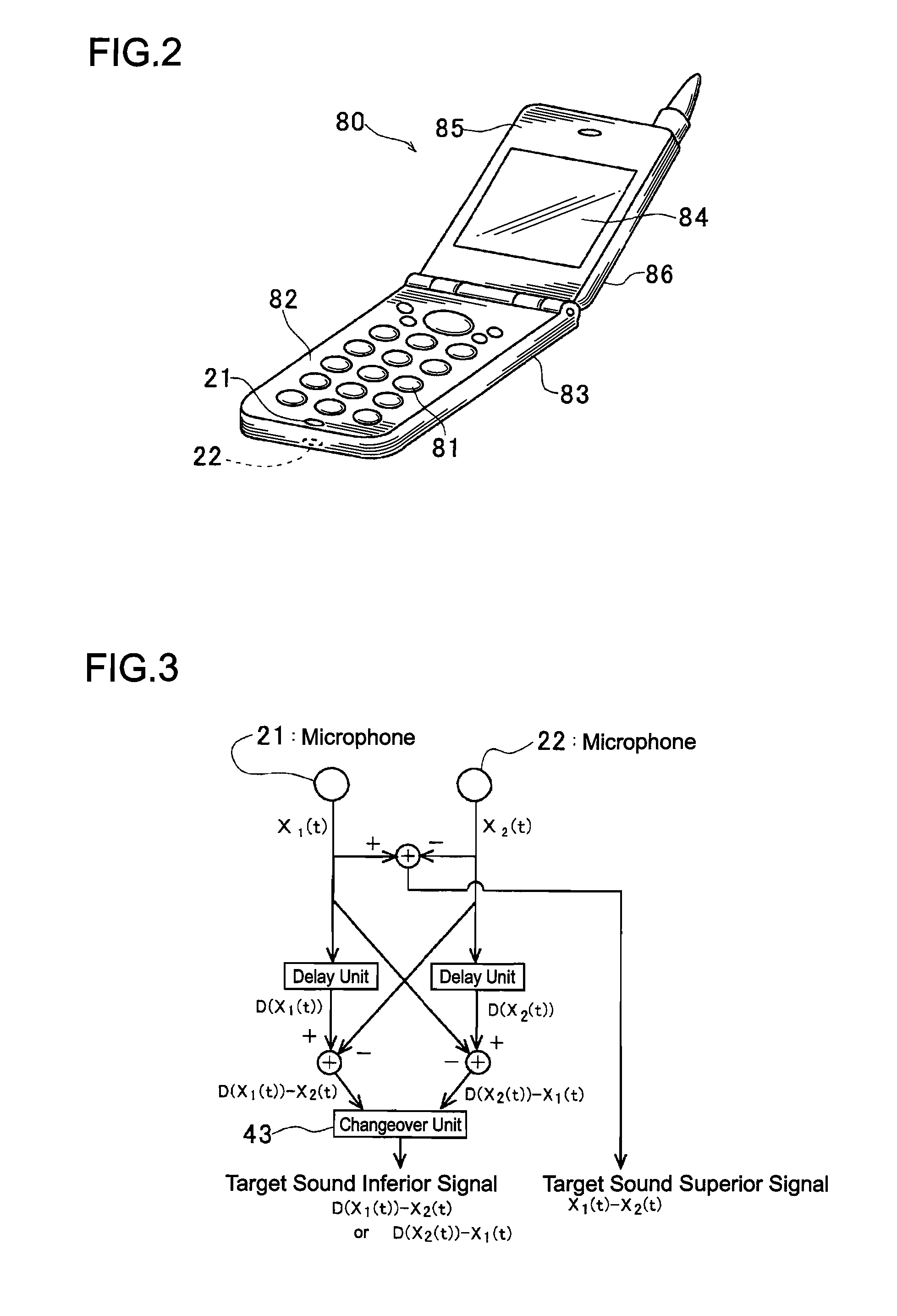
[0258]FIG. 1 illustrates the general structure of a sound source separation system 10 according to the first embodiment of the invention. FIG. 2 illustrates the structure of a cellular phone 80 equipped with the sound source separation system 10. FIG. 3 illustrates the structure of a part of the sound source separation system 10 that performs directivity control. FIG. 4 is an explanatory diagram for a portion that generates a first target sound inferior signal in the part that performs directivity control in FIG. 3. FIG. 5 illustrates the directional characteristics of a target sound superior signal and the first target sound inferior signal used in a normal mode, FIG. 6 illustrates the directional characteristics of the target sound superior signal and second target sound inferior signal used in a changeover mode, and FIG. 7 illustrates directional characteristics with FIGS. 5 and 6 spread out to take a horizontal axis as a direction (angle) θ. FIG. 8 is an explanatory diagram for ...
second embodiment
[0294]FIG. 9 illustrates the general structure of a sound source separation system 200 according to the second embodiment of the invention. FIG. 10 illustrates directional characteristics of a target sound superior signal and target sound inferior signal, and FIG. 11 illustrates directional characteristics with FIG. 10 spread out to take a horizontal axis as a direction (angle) θ. The sound source separation system 200 of the second embodiment is a system relating to .
[0295]With reference to FIG. 9, the sound source separation system 200 comprises two microphones 221, 222, disposed in such a manner as to be spaced away, a target sound superior signal generator 230 which generates a target sound superior signal by performing a linear combination process for emphasizing a target sound on a time domain using the received sound signals of the two microphones 221, 222, a target sound inferior signal generator 240 which generates a target sound inferior signal to be paired with the target...
third embodiment
[0311]FIG. 12 illustrates the general structure of a sound source separation system 300 according to the third embodiment of the invention. FIG. 13 illustrates the respective directional characteristics of first and second target sound superior signals and target sound inferior signal, and FIG. 14 illustrates directional characteristics with FIG. 13 spread out to take a horizontal axis as a direction (angle) θ. The sound source separation system 300 of the third embodiment is a system relating to .
[0312]With reference to FIG. 12, the sound source separation system 300 comprises two microphones 321, 322 disposed as to be spaced away from each other, a target sound superior signal generator 330 that generates first and second target sound superior signals by performing a linear combination process for emphasizing a target sound on a time domain using the received sound signals of the two microphones 321, 322, a target sound inferior signal generator 340 that generates a target sound i...
PUM
 Abstract
Description
Claims
Application Information
 - R&D
- Intellectual Property
- Life Sciences
- Materials
- Tech Scout
- Unparalleled Data Quality
- Higher Quality Content
- 60% Fewer Hallucinations
Browse by: Latest US Patents, China's latest patents, Technical Efficacy Thesaurus, Application Domain, Technology Topic, Popular Technical Reports.
© 2025 PatSnap. All rights reserved.Legal|Privacy policy|Modern Slavery Act Transparency Statement|Sitemap|About US| Contact US: help@patsnap.com


