Engine start device
a technology of engine start and start time, which is applied in the direction of electric generator control, motor/generator/converter stopper, instruments, etc., can solve the problems of prolonged stop-idling time, and achieve the effect of enhancing the starting performance of the engine and achieving more torqu
- Summary
- Abstract
- Description
- Claims
- Application Information
AI Technical Summary
Benefits of technology
Problems solved by technology
Method used
Image
Examples
first exemplary embodiment
[0035]Hereinafter, the structure of the first exemplary embodiment will be described with reference to FIG. 1 through FIG. 5.
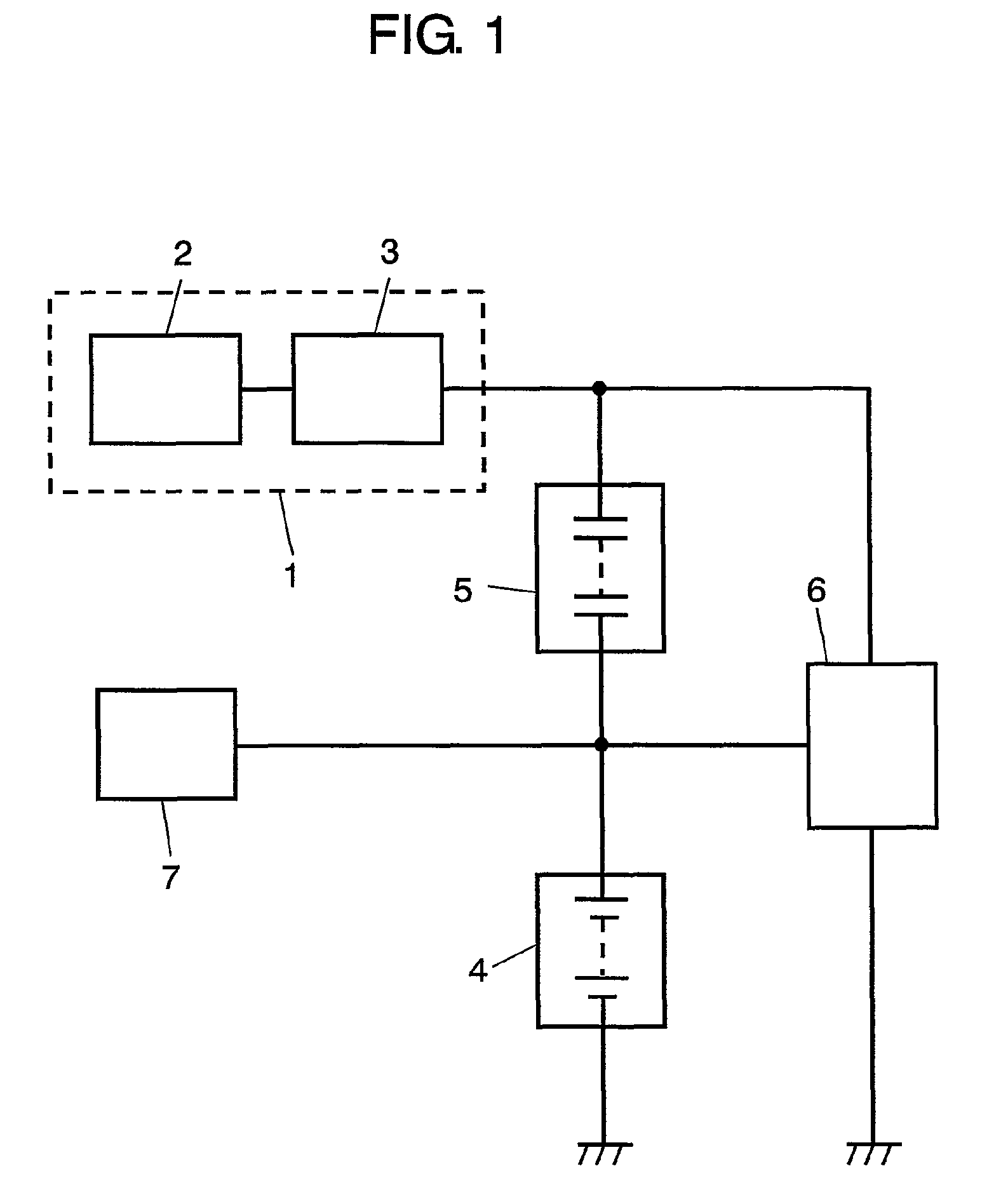
[0036]FIG. 1 is a circuit diagram showing the structure of an engine start device in accordance with the first exemplary embodiment of the present invention. Starter 1 in FIG. 1, which is connected to the driving system of the engine, is formed of starter motor 2 and starter relay 3. Generator 7 is connected to the driving system of the engine. Battery 4 is a lead acid battery with a voltage rating of 12V. Electric double layer capacitor 5 is connected between starter 1 and battery 4. An input terminal of DC / DC converter 6 is connected to the junction point of generator 7 and battery 4 and an output terminal of converter 6 is connected to the junction point of starter 1 and electric double layer capacitor 5.
[0037]How to start the engine in the engine start device structured above is described hereinafter.
[0038]Prior to the initial start of the engine, receivin...
second exemplary embodiment
[0067]Hereinafter, the structure of the second exemplary embodiment will be described with reference to FIG. 6 and FIG. 7.
[0068]FIG. 6 is a circuit diagram showing the structure of an engine start device in accordance with the second exemplary embodiment of the present invention. In FIG. 6, like parts are identified by the same reference numerals as in FIG. 1 and the explanation thereof will be omitted.
[0069]As is shown in FIG. 6, diode 10 is connected in parallel to electric double layer capacitor 5. The cathode of diode 10 is connected to the positive pole of electric double layer capacitor 5.
[0070]Now will be described the engine start operation of the engine start device having the structure above.
[0071]In the initial start of the engine, that is, under the condition where electric double layer capacitor 5 has no charge or lack of charge, when starter relay 3 is turned ON, the voltage of battery 4 is applied to starter motor 2 via diode 10, so that electric current is fed to sta...
third exemplary embodiment
[0082]Hereinafter, the structure of the third exemplary embodiment will be described with reference to FIG. 8 and FIG. 9.
[0083]The structure of the embodiment differs from those of the first and the second embodiments in that the DC / DC converter has a two-way structure. In the structure of the embodiment, like parts are identified by the same reference numerals as in the structures described in the previous two embodiments and the explanation hereinafter will be focused on the difference.
[0084]FIG. 8 is a circuit diagram showing the structure of an engine start device in accordance with the third exemplary embodiment of the present invention. DC / DC converter 61 having a two-way circuit structure also improves the performance of the engine in start-up operation.
[0085]Now will be described the effect brought by two-way DC / DC converter 61.
[0086]FIG. 8 shows an inverting chopper circuit driven on a synchronous rectification system as an example of a two-way converter. Switching element ...
PUM
| Property | Measurement | Unit |
|---|---|---|
| voltage rating | aaaaa | aaaaa |
| voltage rating | aaaaa | aaaaa |
| voltage rating | aaaaa | aaaaa |
Abstract
Description
Claims
Application Information
 - R&D
- Intellectual Property
- Life Sciences
- Materials
- Tech Scout
- Unparalleled Data Quality
- Higher Quality Content
- 60% Fewer Hallucinations
Browse by: Latest US Patents, China's latest patents, Technical Efficacy Thesaurus, Application Domain, Technology Topic, Popular Technical Reports.
© 2025 PatSnap. All rights reserved.Legal|Privacy policy|Modern Slavery Act Transparency Statement|Sitemap|About US| Contact US: help@patsnap.com


