
Rotary mower blade removal and reinstallation device

a rotary mower and blade technology, applied in the field of lawn mower blade removal and installation, can solve the problems of not being able to install the device over the blade, not being able to work with the mulching mower or the multiple-blade mulching mower deck, and rendering it cost-prohibitive to potential users, so as to minimize the cost of fabrication

Inactive Publication Date: 2012-07-03
HENSHAW GEORGE
View PDF11 Cites 6 Cited by
  • Summary
  • Abstract
  • Description
  • Claims
  • Application Information

AI Technical Summary

Benefits of technology

"The invention is a device that allows for the safe removal and installation of rotary mower blades. It is designed to fit over a lawn mower blade acting as a stop to blade rotation. The device is easy to use, fast, and securely secures the blades in place. It can be used on different types of mower blades and does not require adjustment for different blade widths and lengths. The device is also inexpensive to manufacture and can be used on both single- and multiple-blade mower decks."

Problems solved by technology

The device will not work with a mulching mower or multiple-blade mulching mower deck because the blade housing is circular and provides no surface against which to jam the blade.
Further, because of the circular blade housing, it would not be possible to install the device over the blade.
This device requires significant raw material and significant fabrication likely rendering it cost-prohibitive to potential users.
Blades typically require substantially more force to remove than to install and riding mower blades can require 120 pounds of torque or more to install.
The operator will not have a free hand to stabilize the wrench on the blade retaining bolt or nut.
This device requires significant raw material and significant fabrication likely rendering it cost-prohibitive to potential users.
It would require significant personal strength as there is limited, if any, leverage advantage.
Blades typically require substantially more force to remove than to install and riding mower blades can require 120 pounds of torque to install.
The operator will also not have a free hand to stabilize the wrench on the blade retaining bolt.
This device requires significant raw material and significant fabrication likely rendering it cost-prohibitive to potential users.
It is intended for use on single-blade mower decks so it would not be useful for multiple-blade decks typical of riding and commercial mowers.
Significant fabrication is required likely rendering it cost-prohibitive to potential users.
Further, it would not work on most fabricated metal decks (FIG. 13) (as opposed to stamped decks) which are typically employed by manufacturers of commercial quality mowers.
However, it is unsafe to turn any mower upside down without first draining the fuel tank because of the hazard of leaking fuel.
It could not be used effectively in the limited visibility and accessibility conditions under a riding mower.
The tool could fall off because of the open space between the stop pins.
Blades typically require substantially more force to remove than to install and riding mower blades can require 120 pounds of torque to install.
The operator will also not have a free hand to stabilize the wrench on the blade retaining nut or bolt.
This device requires significant raw material and significant fabrication likely rendering it cost-prohibitive to potential users.
Blades typically require substantially more force to remove than to install and riding mower blades can require 120 pounds of torque to install.
The operator will also not have a free hand to stabilize the wrench on the blade retaining bolt.
This device requires significant raw material and significant fabrication likely rendering it cost-prohibitive to potential users.
Further, it would not work on most fabricated metal decks (as opposed to stamped decks) which are typically employed by manufacturers of commercial quality mowers.
While all of the above devices may fulfill their respective particular objectives, they all have limitations ranging from limited application to difficulty to use to expensive fabrication.

Method used


Image

  • Rotary mower blade removal and reinstallation device
  • Rotary mower blade removal and reinstallation device
  • Rotary mower blade removal and reinstallation device

Examples


Embodiment Construction

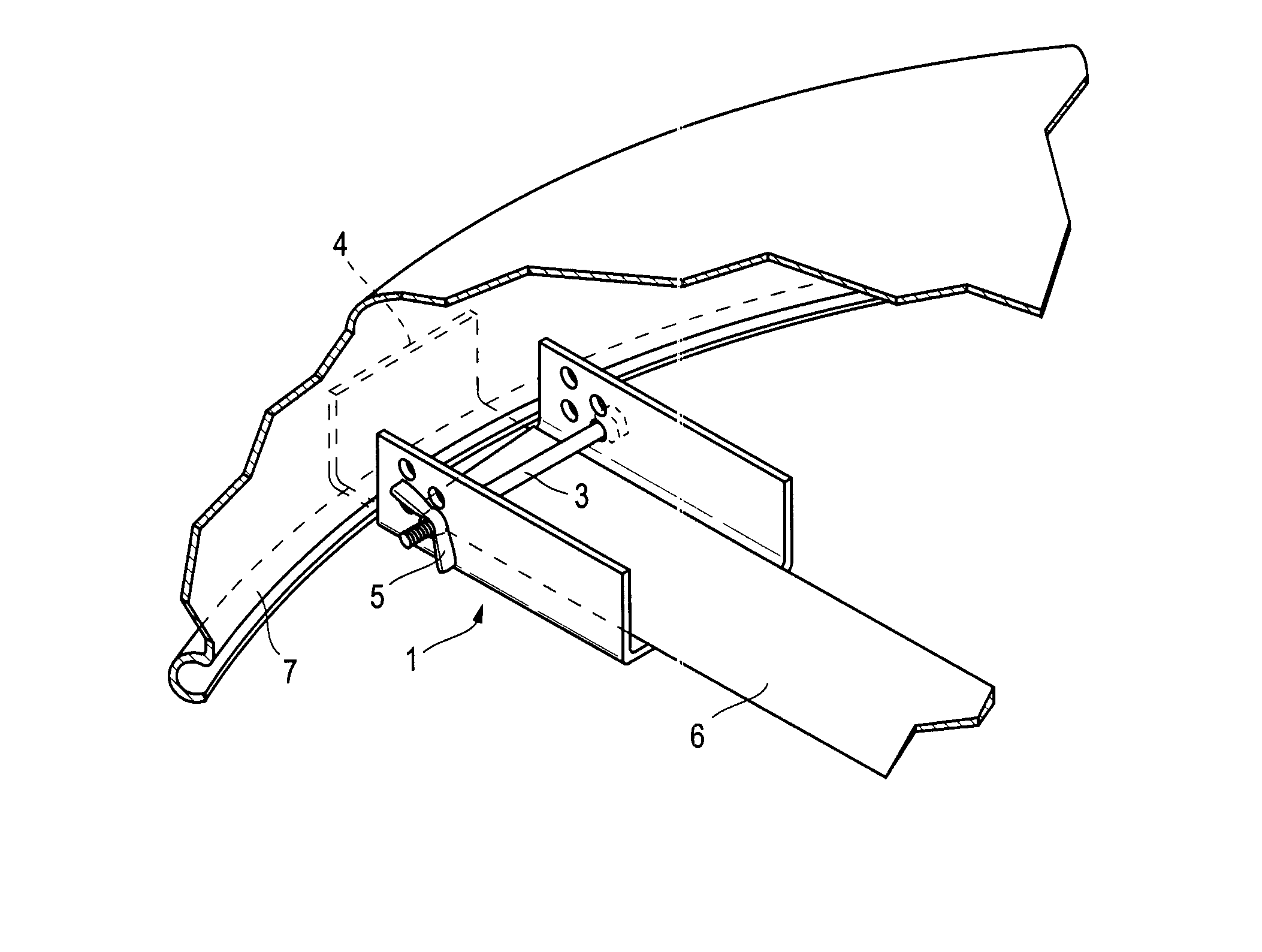
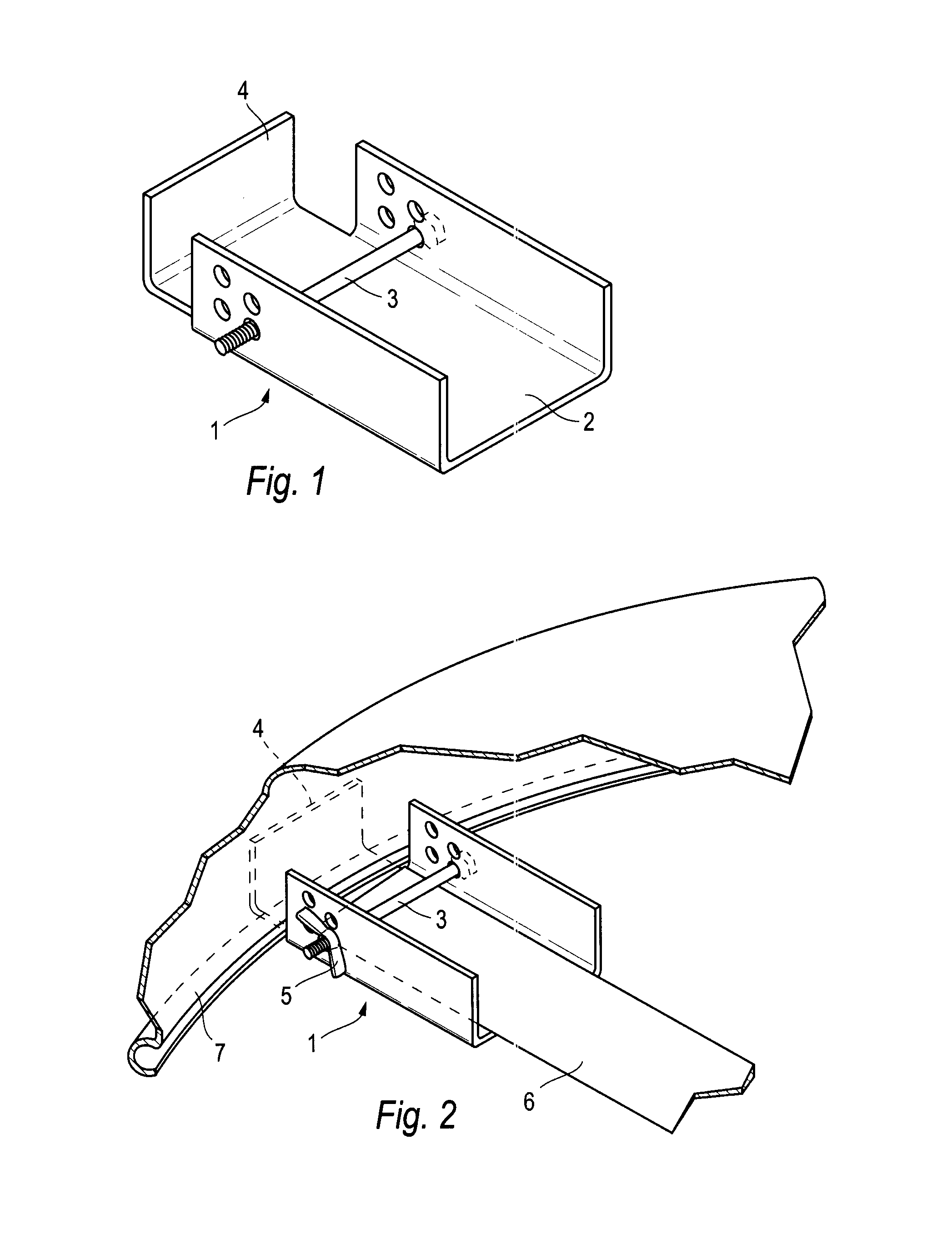
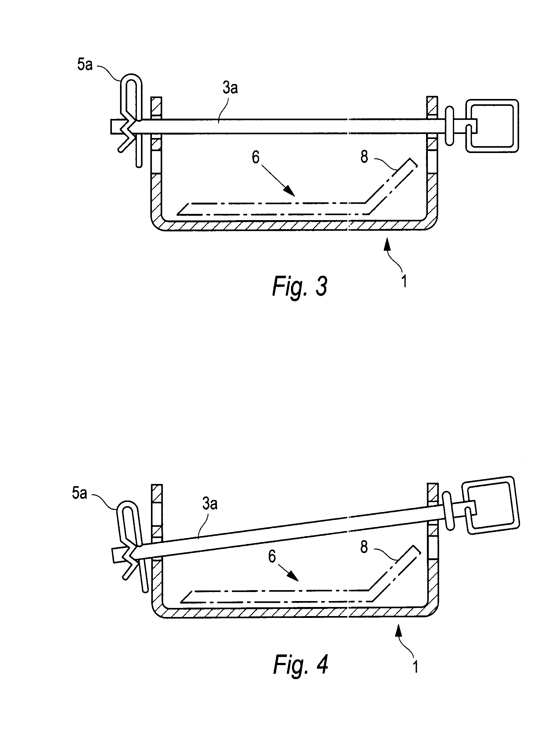
[0042]This device is constructed of steel or aluminum or composite or any other material sufficiently strong. It can be constructed of one piece of material formed by stamping bending or any similar method. It can also be constructed of pre-formed rectangular tubing with one side removed and the exterior restriction leg formed by bending. It can also be constructed of multiple angles cut to size and attached together such as by welding. It can also be constructed by casting in a mold. It can be retained on the blade solely by holding with one hand. Alternately, it can be retained on the blade with any of a number of pinning devices ranging from a toggle pin to a bolt to a bolt and nut to a pin with retaining clip. It can also be retained by a secondary “C” shaped retainer (18) which is slid over the device's open side (FIG. 9). For embodiments utilizing a pinning method, the device may have holes drilled, molded or punched completely through said tubing to allow a pin or shaft 3 (FI...


PUM

PropertyMeasurementUnit
torqueaaaaaaaaaa
gravityaaaaaaaaaa
pressureaaaaaaaaaa

Abstract

A device constructed of a material strong enough to withstand the torque of a typical air wrench or cheater bar used by a lawn mower repair shop or a homeowner. One end of the device must have an opening and be of the size as to allow a lawn mower blade to be inserted inside of it. The portion containing the tip of the blade may include a leveler and / or retainer to raise the device to approximately the horizontal plane of the mower blade and the lower edge of the mower deck. The device includes a restriction leg to provide a prop against any protuberance on the side of a single-blade mower deck or on the side or within the deck on a multi-blade mower deck. To provide economics for manufacturing, one size should fit most blades and the device should require a limited quantity of materials and fabrication.

Description

BACKGROUND FIELD OF INVENTION[0001]This invention relates to the removal and installation of lawn mower blades, specifically to produce devices to be placed upon or over lawn mower blades to assist in stopping rotation of said blades so they may be safely removed and / or installed.[0002]For peak efficiency, lawn mower blades should be re-sharpened or replaced regularly. It is difficult at best and even dangerous to remove any blade retaining nut or bolt, especially so if the nut or bolt has been over-tightened or rusted in place. The problem is to lock the blade positively against rotation so the high torque necessary to loosen the blade retaining nut or bolt can be applied with a wrench. Holding the blade with a gloved hand does not guarantee enough leverage to loosen the nut especially because blades are routinely installed with a torque tightness of 60 to 120 foot pounds or more and may tend to tighten even more in use.[0003]The typical device to assist users in this procedure tha...

Claims


Application Information

Patent Timeline
Patent Type & Authority Patents(United States)
IPC IPC(8): B23Q1/00B23Q7/04B23Q3/00B08B5/00A47L9/00A47L5/00B23P19/04A01D34/00A01D67/00B25B27/00B24B19/00B24D11/00
CPCA01D34/001B25B13/48B25B23/0085B25B27/00Y10T29/53961Y10T29/53687Y10T29/53991
Inventor HENSHAW, GEORGE
Owner HENSHAW GEORGE
Learn More