
Ultra-wide band slow light structure using plasmonic graded grating structures

a plasmonic graded grating and ultra-wide band technology, applied in the direction of instruments, sensing record carriers, sensing by electromagnetic radiation, etc., can solve the problems of limited working wavelengths, narrow bandwidth, and strong temperature dependen

Active Publication Date: 2012-06-26
LEHIGH UNIVERSITY
View PDF8 Cites 20 Cited by
  • Summary
  • Abstract
  • Description
  • Claims
  • Application Information

AI Technical Summary

Benefits of technology

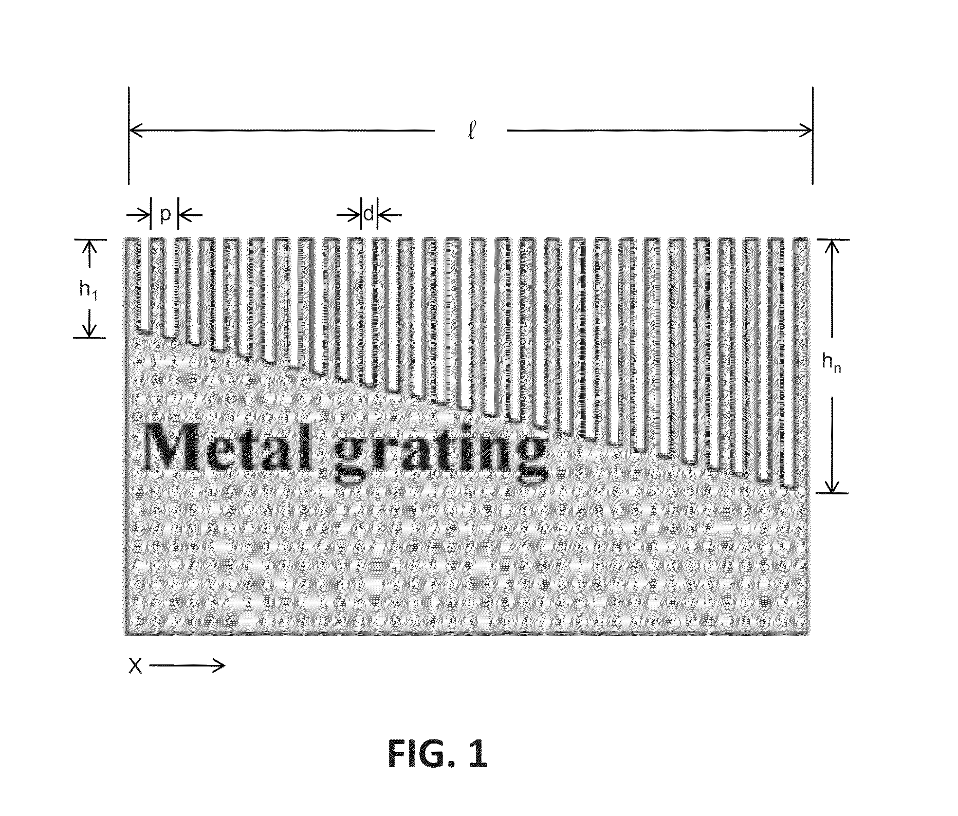
The patent describes a system that can slow down light waves using a metal layer with a graded grating structure. The depth of the grating structure is designed to cause different wavelengths of light to be slowed down at different locations along the grating. This results in a more gradual change in the speed of the light as it passes through the system, which can be useful in various applications such as optical communication.

Problems solved by technology

The use of electronic states to coherently store the optical information, however, imposes severe constraints in the scheme, including narrow bandwidth, limited working wavelengths and strong temperature dependence.
While promising steps have been taken towards slowing light in solid-state media and semiconductor nanostructures operating at room temperature, “stopping” light completely and implementation of slow light structures on a chip including optoelectronic devices remains a great challenge.

Method used


Image

  • Ultra-wide band slow light structure using plasmonic graded grating structures
  • Ultra-wide band slow light structure using plasmonic graded grating structures
  • Ultra-wide band slow light structure using plasmonic graded grating structures

Examples


Embodiment Construction

[0025]This description of the exemplary embodiments is intended to be read in connection with the accompanying drawings, which are to be considered part of the entire written description. In the description, relative terms such as “lower,”“upper,”“horizontal,”“vertical,”“above,”“below,”“up,”“down,”“top” and “bottom” as well as derivative thereof (e.g., “horizontally,”“downwardly,”“upwardly,” etc.) should be construed to refer to the orientation as then described or as shown in the drawing under discussion. These relative terms are for convenience of description and do not require that the apparatus be constructed or operated in a particular orientation. Terms concerning attachments, coupling and the like, such as “connected” and “interconnected,” refer to a relationship wherein structures are secured or attached to one another either directly or indirectly through intervening structures, as well as both movable or rigid attachments or relationships, unless expressly described otherw...


PUM

PropertyMeasurementUnit
grating depthaaaaaaaaaa
frequenciesaaaaaaaaaa
grating depthaaaaaaaaaa

Abstract

A slow light system includes a substrate and a metal layer formed thereon, the metal layer having a graded grating structure formed at a surface thereof, wherein the grating depth of the grating structure is sized such that surface-plasmon polariton dispersion behavior of the grating structure differs at different respective locations along the grating structure. Different wavelengths of incident light waves can be slowed at the respective locations along the grating structure.

Description

CROSS-REFERENCE TO RELATED APPLICATIONS[0001]This application claims priority to U.S. Provisional Patent Application No. 61 / 109,549 entitled “‘RainbowTrapping and Releasing For Surface Waves: An Ultra-Wide Band Slow Light Structure”, filed Oct. 30, 2008, the entirety of which is hereby incorporated by reference herein.GOVERNMENT LICENSE RIGHTS[0002]The U.S. Government has a paid-up license in this invention and the right in limited circumstances to require the patent owner to license others on reasonable terms as provided for by the terms of Grant # CBET-0608742 awarded by the National Science Foundation.FIELD OF THE INVENTION[0003]The present invention relates to apparatuses for the control of light, and more specifically to structures for slowing incident light.BACKGROUND OF THE INVENTION[0004]It is known that light can be slowed down in the vicinity of resonances in dispersive materials. In order to reduce the group velocity (vg) of light coherently, there are two major approac...

Claims


Application Information

Patent Timeline
Patent Type & Authority Patents(United States)
IPC IPC(8): G02F1/01G02B26/08G02B26/00
CPCG02B5/008G02F1/0102G02F1/29G02F1/3511G02F2201/30G02F2203/10
Inventor GAN, QIAOQIANGFU, ZHANDING, YUJIE J.BARTOLI, FILBERT J.
Owner LEHIGH UNIVERSITY
Learn More