Frequency conversion

a frequency conversion and frequency technology, applied in the field of frequency conversion, can solve the problems of affecting the output voltage of the mixer, the snr of the received signal, and the noise and intermodulation of the active gilbert mixer, so as to reduce the attractiveness of the use of parallel resonance lc tanks in order to convert the mixer output current into an output voltag

Inactive Publication Date: 2012-06-19
NXP BV
View PDF17 Cites 5 Cited by
  • Summary
  • Abstract
  • Description
  • Claims
  • Application Information

AI Technical Summary

Benefits of technology

[0017]According to the invention there is provided a frequency conversion circuit configured to mix a first input signal at a first frequency with a second input signal at a second frequency to provide an output intermediate frequency signal, the circuit comprising:

Problems solved by technology

The DC bias current source also connects to the IF amplifier input and forms a significant source of low frequency noise, degrading the signal-to-noise ratio (SNR) of the received signal.
Compared to passive switching mixers, active Gilbert mixers tend to have somewhat inferior performance with regard to (1 / f) noise and intermodulation.
The use of a parallel resonance LC tank tuned to the IF frequency in order to convert the mixer output current into an output voltage is less attractive due to the size and associated cost of providing integrated inductors.
For the case of a 10 bit mixing DAC the noise degradation by current sources ID was found to be unacceptably high.
In practice however, the noise contributed by Is can be neglected compared to the noise generated by the bias current source ID.
Commutation is effective in attenuating the low frequency noise, but has the disadvantage of potentially introducing an unwanted spurious signal if applied with a frequency different from the mixing frequency.

Method used


Image

  • Frequency conversion
  • Frequency conversion
  • Frequency conversion

Examples


Embodiment Construction

[0032]The intermediate frequency output circuit may be an intermediate frequency amplifier, or alternatively could comprise a resistor network.

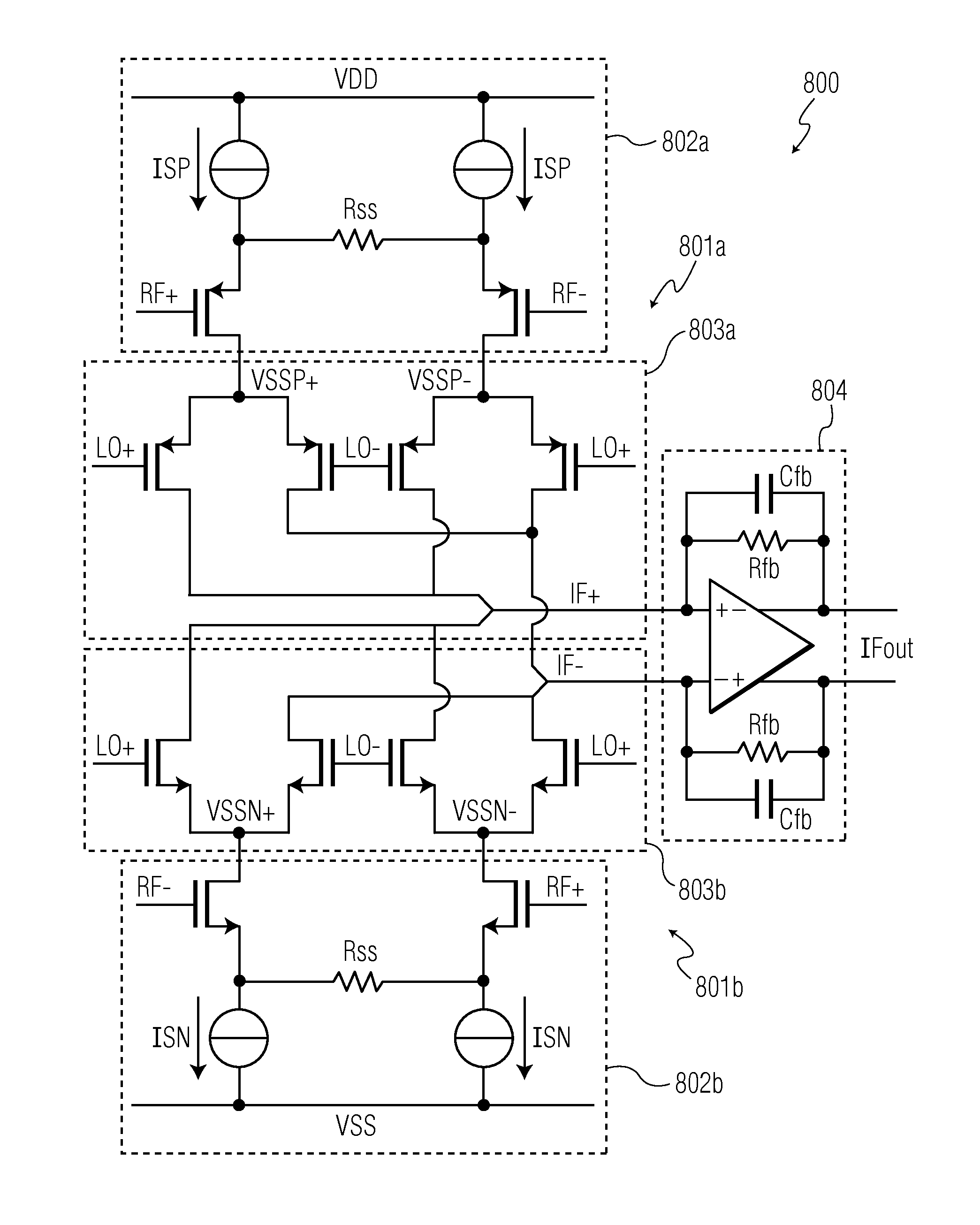
[0033]The voltage to current converter and Gilbert mixer of each mixing module are preferably configured to share a common DC bias current. This reduces the noise contribution of the circuit.

[0034]The inputs of each voltage to current converter are preferably AC coupled to the first input signal, to enable an optimal DC biasing of the first and second voltage to current converter.

[0035]The transistors are typically CMOS transistors of PMOS and NMOS type, although implementations using bipolar junction transistors may be envisaged. By introducing complementary N type and P type active Gilbert mixers, the above mentioned problems relating to a DC bias current source can be avoided. The proposed mixer structure therefore has much better noise properties, and can, for example, advantageously be used as a building block in harmonic rejection mixer...


PUM


Abstract

A frequency conversion circuit configured to mix a first input signal (RF+,RF−) at a first frequency with a second input signal (LO+,LO−) at a second frequency to provide an output intermediate frequency signal (IFout), the circuit comprising: first and second mixing modules, each mixing module comprising a voltage to current converter configured to receive the first input signal (RF+,RF−) and connected to a Gilbert mixer configured to receive the second input signal (LO+,LO−); an intermediate frequency output circuit having inputs connected to receive an intermediate frequency current signal (IF+,IF−) from outputs of each of the Gilbert mixers and an output configured to provide the output intermediate frequency voltage signal (IFout), wherein the first and second mixing modules comprise transistors which are complementary to each other.

Description

[0001]This application claims the priority of European patent application no. 09252264.8, filed on Sep. 23, 2009, the contents of which are incorporated by reference herein.BACKGROUND OF THE INVENTION[0002]An integrated active Gilbert mixer typically needs a DC bias current source at the mixer output. The DC bias current source also connects to the IF amplifier input and forms a significant source of low frequency noise, degrading the signal-to-noise ratio (SNR) of the received signal.[0003]An example of an active Gilbert mixer 102 forming part of a mixer circuit 100 is illustrated in FIG. 1. The mixing circuit 100 comprises a voltage to current converter 101 connected to a Gilbert mixer 102. The voltage to current converter 101 comprises a pair of NMOS transistors 103a, 103b having their sources connected across a resistor Rss and to a voltage supply line Vss via respective current sources 104a, 104b, each supplying a bias current Is through the transistors 103a, 103b. The gates of...

Claims


Application Information

Patent Timeline
Patent Type & Authority Patents(United States)
IPC IPC(8): G06F7/44G06G7/16
CPCH03D7/1441H03D7/166H03D7/1433H03D7/1458H03D7/1483H03D2200/0043H03D2200/0084
Inventor DE JONG, GERBEN WILLEMBREKELMANS, JOHANNES HUBERTUS ANTONIUS
Owner NXP BV
Why Eureka
Try Eureka