
Fluidic connectors and microfluidic systems

a technology of microfluidic systems and connectors, applied in the field of microfluidic systems and components thereof, can solve the problems of dead volume of many world-to-chip connectors, inability to match the volume of on-chip volume with respect to volume, and high cost and sophistication of fluid delivery to the platform

Active Publication Date: 2012-06-19
OPKO DIAGNOSTICS
View PDF130 Cites 98 Cited by
  • Summary
  • Abstract
  • Description
  • Claims
  • Application Information

AI Technical Summary

Benefits of technology

The patent describes devices and methods for performing analyses in microfluidic systems. The devices include microfluidic channels and a fluidic connector that can be connected to a substrate. The fluidic connector has a fluid path with an inlet and an outlet, and the device can be used without recirculating fluid. The method involves connecting the device to a substrate and then introducing a controlled volume of fluid into the fluid path. The device can also have a reaction area for detecting chemical or biological reactions. The patent also describes a method for detecting a chemical or biological reaction in a microfluidic system without the need for recirculation of fluid. Overall, the patent provides devices and methods for performing analyses in microfluidic systems with improved efficiency and accuracy.

Problems solved by technology

While various microfluidic devices and methods, such as microfluidic assays, can provide inexpensive, sensitive and accurate analytical platforms, fluid delivery to the platform can add a level of cost and sophistication, as the operation of microfluidic devices often requires the ability to exchange fluids between the device itself and the outside world.
The major problem associated with world-to-chip connection is the mismatch between the volumes used on-chip (e.g., femtoliters to microliters) with respect to the volumes typically handled at the bench (e.g., microliters to liters).
For instance, many world-to-chip connectors have dead volume, e.g., wasted volume that may lie at the core of the connector itself.
In practice, the dead volume of many devices can often be higher than the volume of sample analyzed by the chip; this is an undesired effect for applications that rely on small sample / reagent consumption.

Method used


Image

  • Fluidic connectors and microfluidic systems
  • Fluidic connectors and microfluidic systems
  • Fluidic connectors and microfluidic systems

Examples


example 1

Fabrication of Microfluidic Channels in a Substrate

[0189]A method for fabricating a microfluidic channel system is described.

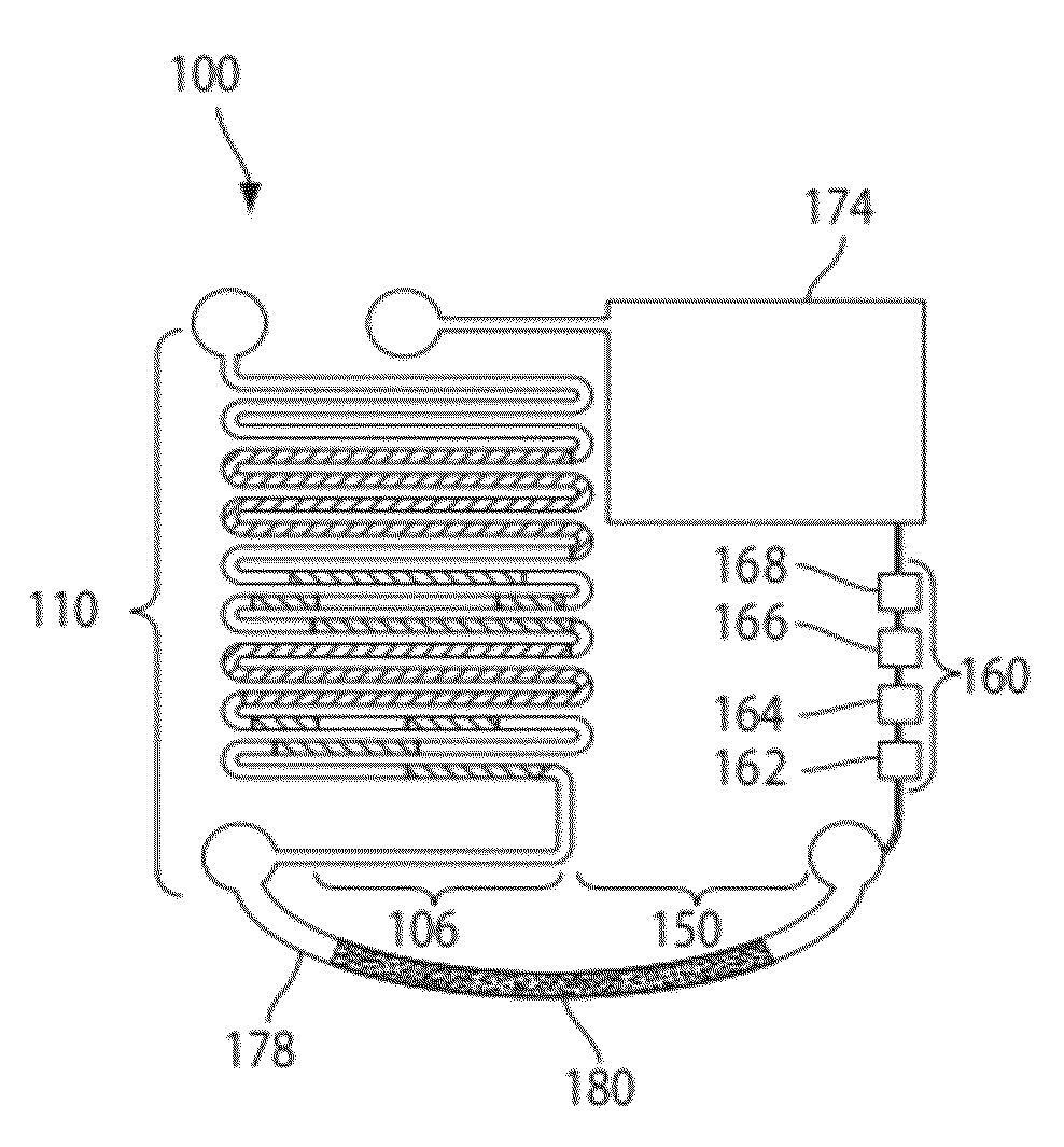
[0190]The layouts of the channel system were designed with a computer-aided design (CAD) program and are illustrated in FIGS. 3 and 4. The microfluidic devices were formed in poly(dimethylsiloxane) Sylgard 184 (PDMS, Dow Corning, Distrelec, Switzerland) by rapid prototyping using masters made in SU8 photoresist (MicroChem, Newton, Mass.). The masters were produced on a silicon wafer and were used to replicate the negative pattern in PDMS. The masters contained two levels of SU8, one level with a thickness (height) of ˜50 μm defining the channels in the immunoassay area, and a second thickness (height) of ˜250 μm defining the reagent storage and waste areas. The master was silanized with (tridecafluoro-1,1,2,2-tetrahydrooctyl)trichlorosilane (ABC-R, Germany). PDMS was mixed according to the manufacturer's instructions and poured onto the master. After polymeriz...

example 2

Storing Reagents in a Microfluidic System

[0192]This example describes a method for storing dry and liquid reagents in a microfluidic system.

[0193]Dry and wet reagents were stored in the microfluidic systems shown in FIGS. 3-5 and 14. To store dry reagents, drops of biomolecules were placed onto the detection zones of the substrate. After 30 min, the solution was removed and the surface of the substrate modified with proteins was rinsed with buffer. The surface was dried with compressed nitrogen for 20 s, and then the substrate was sealed against a cover. The cover was either a plate of polystyrene (in the case PDMS substrates) (NUNC Omnitray, VWR, Switzerland) or a biocompatible adhesive (in the case of polystyrene substrates). When a biocompatible adhesive was used, the polystyrene substrate was drilled to obtain access holes prior to application of the cover. In a different approach, the holes were formed in the thermoplastic during the injection molding process by using pillars i...

example 3

Performing an Immunoassay by Loading a Sample Using an Open-Ended Capillary Tube

[0198]This example shows that an immunoassay can be performed by loading a sample using an open-ended capillary tube and using reagents stored on a microfluidic substrate.

[0199]The microfluidic system of FIG. 7 was fabricated using the method described in Example 1. This system included four sections: a reagent storage area, a sample loading area, an immunoassay area and a waste area. The reagent storage area was pre-filled with reagents required to perform an immunoassay for the detection of total human IgG in whole blood: antibody solutions, washing buffers and amplification reagents (either enzymatic substrates or silver amplification reagents) using the method described in Example 2. These reagents were presented as ready-to-use aqueous solutions loaded as a sequence of liquid plugs, separated from each other by air gaps.

[0200]A sample of blood from a donor was obtained and the sample was loaded into...


PUM

PropertyMeasurementUnit
volumeaaaaaaaaaa
volumeaaaaaaaaaa
diameteraaaaaaaaaa

Abstract

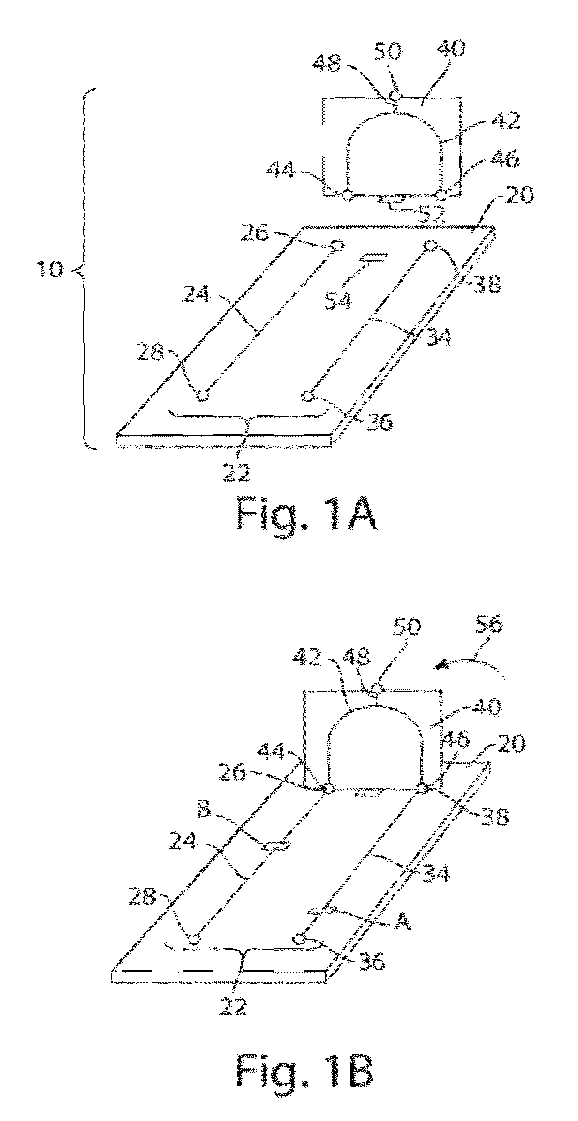
Fluidic connectors, methods, and devices for performing analyses (e.g., immunoassays) in microfluidic systems are provided. In some embodiments, a fluidic connector having a fluid path is used to connect two independent channels formed in a substrate so as to allow fluid communication between the two independent channels. One or both of the independent channels may be pre-filled with reagents (e.g., antibody solutions, washing buffers and amplification reagents), which can be used to perform the analysis. These reagents may be stored in the channels of the substrate for long periods amounts of time (e.g., 1 year) prior to use. Prior to connection of the fluid connector and the substrate, the fluid path may be filled with a sample (e.g., blood). The sample may be obtained, for example, by pricking a finger of a user until blood is drawn from the finger into the fluid path (e.g., by capillary forces). Upon connection of the fluidic connector and the channels of the substrate, the sample can pass through a reaction area within the first channel of the substrate. This process can allow components of the sample to interact with components disposed in the reaction area. Afterwards, reagents from the second channel can flow to the reaction area via the fluid path, allowing components in the reaction area to be processed (e.g., amplified to produce detectable signal). Components in the reaction area can then be determined using various methods of detection.

Description

RELATED APPLICATIONS[0001]This application claims priority under 35 U.S.C. §119(e) to U.S. Provisional Patent Application No. 60 / 927,640, filed May 4, 2007, and entitled “Fluidic Connectors and Microfluidic Systems”, which is incorporated herein by reference.FIELD OF INVENTION[0002]The present invention relates generally to microfluidic systems and components thereof, and more specifically, to fluidic connectors, methods, and devices for performing analyses in microfluidic systems.BACKGROUND[0003]The delivery of fluids plays an important role in fields such as chemistry, microbiology and biochemistry. These fluids may include liquids or gases and may provide reagents, solvents, reactants, or rinses to chemical or biological processes. While various microfluidic devices and methods, such as microfluidic assays, can provide inexpensive, sensitive and accurate analytical platforms, fluid delivery to the platform can add a level of cost and sophistication, as the operation of microfluid...

Claims


Application Information

Patent Timeline
Patent Type & Authority Patents(United States)
IPC IPC(8): G01N15/06G01N33/48G01N33/00
CPCB01L3/5027B01L3/565G01N33/5306G01N33/5304G01N33/5302B01L3/563Y10T436/11B01L2200/025B01L2200/027B01L2200/10B01L2200/16B01L2300/0672B01L2300/0861B01L2400/049Y10T436/25Y10T436/2575Y10T403/22G01F22/00B01L3/502715B01L2200/0689B01L3/502707B01L3/502761B01L2200/12B01L2300/021B01L2300/041B01L2300/0627B01L2300/0838B01L2300/12C12Q1/6834G01N21/6428G01N33/54366G01N33/545
Inventor LINDER, VINCENTSTEINMILLER, DAVIDSIA, SAMUEL K.
Owner OPKO DIAGNOSTICS
Learn More