
Image forming apparatus

a technology of image forming apparatus and developing roller, which is applied in the direction of electrographic process apparatus, instruments, optics, etc., can solve the problems of insufficient toner supply from the developing roller to the photoreceptor drum, insufficient toner supply, and inability to stabilize the time period for which the toner is stirred in the developing device, so as to suppress the danger of forming an image of defective quality, prevent the developer from deteriorating excessively, and reduce the probability of occurren

Active Publication Date: 2012-06-12
SHARP KK
View PDF10 Cites 1 Cited by
  • Summary
  • Abstract
  • Description
  • Claims
  • Application Information

AI Technical Summary

Benefits of technology

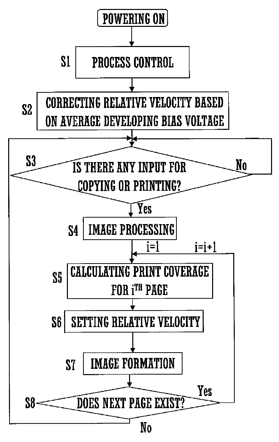
[0011]With this arrangement, the driving velocity of the image bearing member or developer bearing member is adjusted based on the amount of toner required by an image to be formed during image formation. Therefore, even when the amounts of toner required by respective images vary largely during a period of continuous formation of the plural images, an adequate amount of toner can be supplied from the developer bearing member to the image hearing member by appropriately adjusting the driving velocity of the image bearing member or developer bearing member. Even in this case, it is possible to prevent the developer from deteriorating excessively by decelerating the relative velocity, thereby to suppress the danger of forming an image of defective quality. In cases where the amount of toner required by each image is very large, the likelihood of occurrence of a thin spot in a printed image is substantially constant even when the amount of toner to be supplied is increased. Therefore, deterioration of the developer can be prevented effectively by setting the relative velocity to the predetermined value without increasing the relative velocity.

Problems solved by technology

After formation of plural images, however, a time period for which the toner is stirred in the developing device is not stabilized.
Since the amount of charge on the toner varies in accordance with the toner stirring time in the developing device, instable stirring time makes it difficult to uniformalize the image density of the toner patch.
With the driving velocity of the developing roller held constant during continuous image formation, the amount of toner to be supplied from the developing roller to the photoreceptor drum might become excessive or insufficient when the amounts of toner required by the respective images vary largely.
If the driving velocity of the developing roller is sufficiently high, such excess or insufficiency of toner is not likely to occur, but the developer is borne on the developing roller with an increased frequency and, hence, deterioration of the developer progresses easily.
This results in an increased danger of forming an image of defective quality due to occurrence of a pinhole or the like.

Method used


Image

  • Image forming apparatus
  • Image forming apparatus
  • Image forming apparatus

Examples


examples

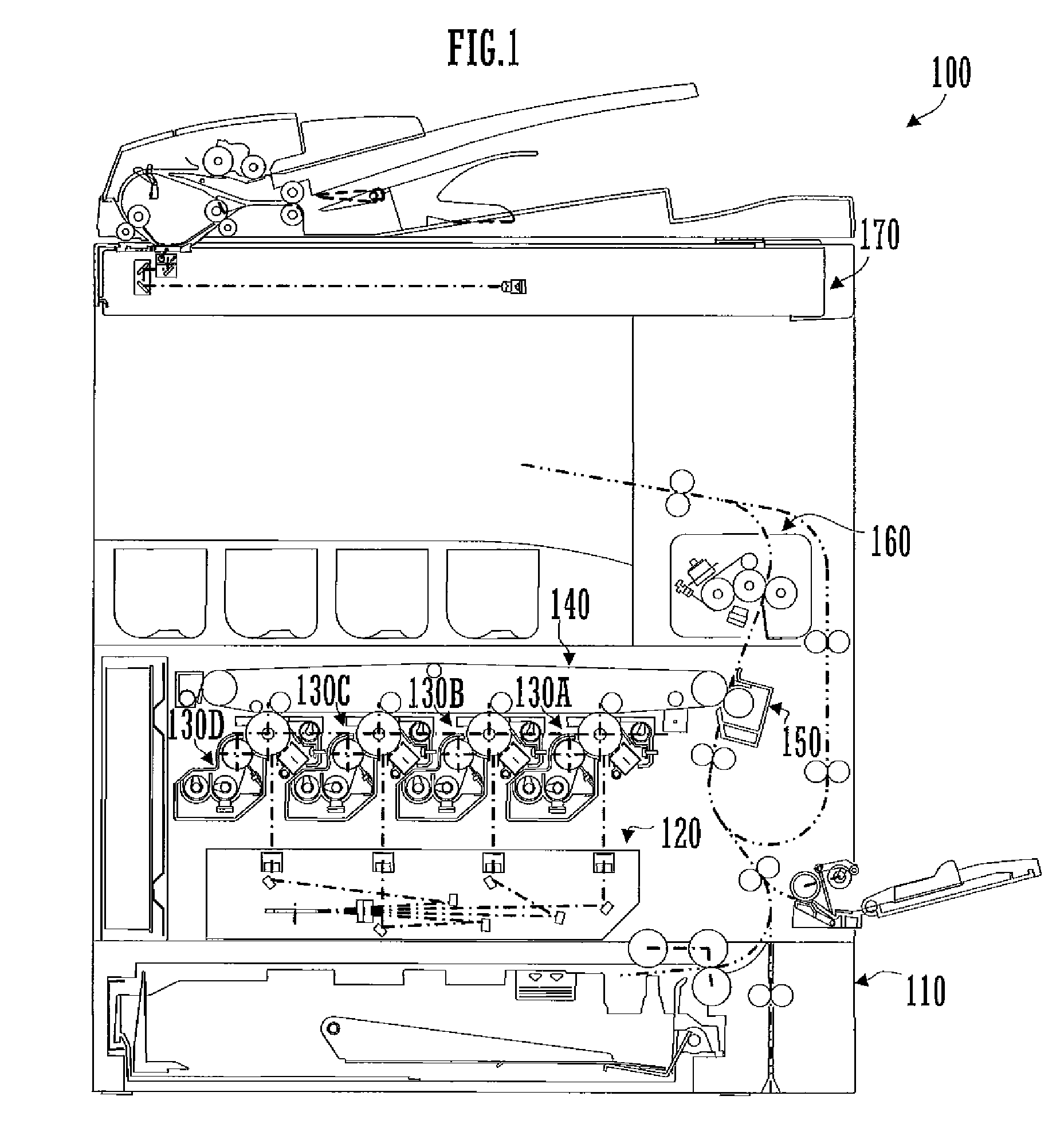
[0081]The following description is directed to the results of image forming experiments using a copier (trade name: MX-7000N, manufactured by SHARP CORPORATION) as an image forming apparatus. In the experiments, the fluidity of a developer was measured using a fluidity measuring device (trade name: VIBRATION TRANSFER FLUIDITY METER, manufactured by ETWAS CORPORATION). The density of an image was measured using a portable spectrocolorimetric densitometer (trade name: X-Rite 939, manufactured by X-Rite Corporate).

Evaluation Experiment in Continuous Printing at a Constant Print Coverage

[0082]Continuous image formation on 10,000 recording sheets was carried out by the copier while keeping constant a combination of the peripheral velocity ratio between the developing roller and the photoreceptor drum and the print coverage. Thereafter, fluidity evaluation was conducted by putting the developer collected from the copier into the fluidity measuring device. Images printed by the copier were...


PUM


Abstract

An image forming apparatus includes a photoreceptor drum, a developing roller, and a control section. The photoreceptor drum is configured to form an electrostatic latent image on a surface thereof in accordance with image data. The developing roller has a surface for bearing a two-component developer at least a partial region of which faces the photoreceptor drum and is configured to be driven so as to feed the developer to the photoreceptor drum. The control section is configured to detect a print coverage for image data to be used during continuous formation of images in accordance with plural image data items and then set a relative velocity of the developing roller to the photoreceptor drum to a higher value when the print coverage is relatively high and set the relative velocity to a lower value when the print coverage is relatively low.

Description

CROSS REFERENCE[0001]This Nonprovisional application claims priority under 35 U.S.C. §119(a) on Patent Application No. 2008-032654 filed in Japan on Feb. 14, 2008, the entire contents of which are hereby incorporated by reference.BACKGROUND OF THE INVENTION[0002]The present invention relates to an electrophotographic image forming apparatus and a method of controlling such an image forming apparatus.Description of the Related Art[0003]An electrophotographic image forming apparatus includes a developing device and a photoreceptor drum and uses a one-component or two-component developer. The one-component developer comprises a toner having a magnetic property, while the two-component developer comprises magnetic particles called “carrier” and a toner.[0004]An image forming apparatus of the type using the two-component developer supplies the toner from a toner cartridge or the like into the developing device. The developing device includes a developing roller having a magnet member the...

Claims


Application Information

Patent Timeline
Patent Type & Authority Patents(United States)
IPC IPC(8): G03G15/08
CPCG03G15/0806G03G15/50
Inventor MAEZAWA, NOBUHIRO
Owner SHARP KK
Learn More