Device and method for operation of a fuel cell

a fuel cell and device technology, applied in the direction of fuel cells, solid electrolyte fuel cells, electrical devices, etc., can solve the problems of high complexity of one of the raw-material gases as a function of the instantaneous feed pressure of the other raw-material gas, and the outlet valve of a gas cylinder or a fuel reservoir of this type cannot be adjusted in practice sufficiently quickly, continuously and accurately for defined pressure changes, etc., to avoid local overloading, reduce volume, and low mass

Active Publication Date: 2009-10-15
DIEHL AEROSPACE GMBH
View PDF7 Cites 1 Cited by
  • Summary
  • Abstract
  • Description
  • Claims
  • Application Information

AI Technical Summary

Benefits of technology

[0012]It is now therefore also superfluous to use an intrinsically conventional initial pressure vessel for the compressor for the oxidant. Its function can also be carried out by the corresponding volume element, such that the resultant additional requirement for installation space for the equalizing container with the two chambers, or for the two chambers with their equalizing channel, is small.
[0013]A beaded metal membrane, for example of the type that is used for aneroid manometers, can be used as a separating wall which extends with a reversible shape change into in each case one of the two volume elements. When a plastic film is used for the separating wall, this need not be elastomeric; it is sufficient for it to be flexible (and, of course, impermeable for the raw-material gases on both sides of it). Since it need not be taut, it just carries out a bulging deformation as a result of the instantaneous overpressure on one of its sides, in order to reduce the volume on the adjacent side. In order to avoid local overloading when stress peaks occur suddenly, this variable-shape separating wall advantageously has an approximately circular edge; alternatively, it is in any case mounted in a round opening in a mounting wall which then itself rests in a gas-tight manner against the internal periphery of the equalizing container. For maximum dynamic response, the separating wall should have low mass and should be easily movable; elastic characteristics (restriction for dynamic response) should advantageously come into effect only at the maximum deflection of the separating wall, in order to protect it.

Problems solved by technology

Pressure regulation, which reacts sufficiently quickly and nevertheless without overshooting, of one of the two raw-material gases as a function of the instantaneous feed pressure of the other raw-material gas is, however, highly complex; in particular, neither the outlet valve of a gas cylinder or a fuel reservoir of this type nor the compressor for the air supply can in practice be adjusted sufficiently quickly, continuously and accurately for defined pressure changes.
Synchronous pressure profiles must be maintained not only during the operation of the cell but also when it is being started up at the start of operation and shut down at the end of operation, in order to avoid loads on one side of the membrane, and this is additionally problematic from the operational point of view and can be coped with only to a restricted extent even with a high degree of active control complexity.
Any control matching between the two gas pressures which interact with one another is, on the other hand, completely impossible from the installation point of view in the fuel cell itself.

Method used


Image

  • Device and method for operation of a fuel cell
  • Device and method for operation of a fuel cell
  • Device and method for operation of a fuel cell

Examples


Embodiment Construction

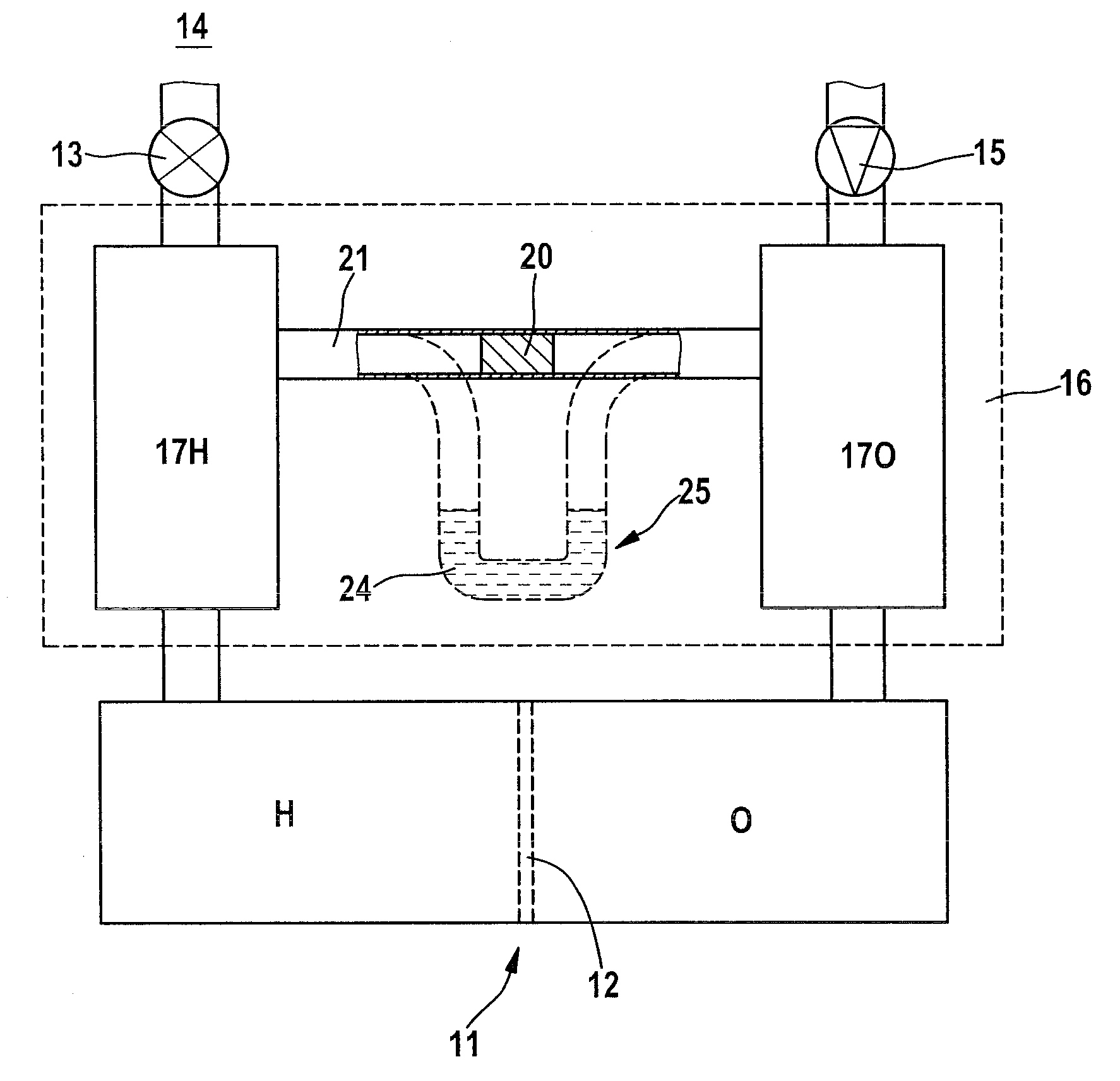
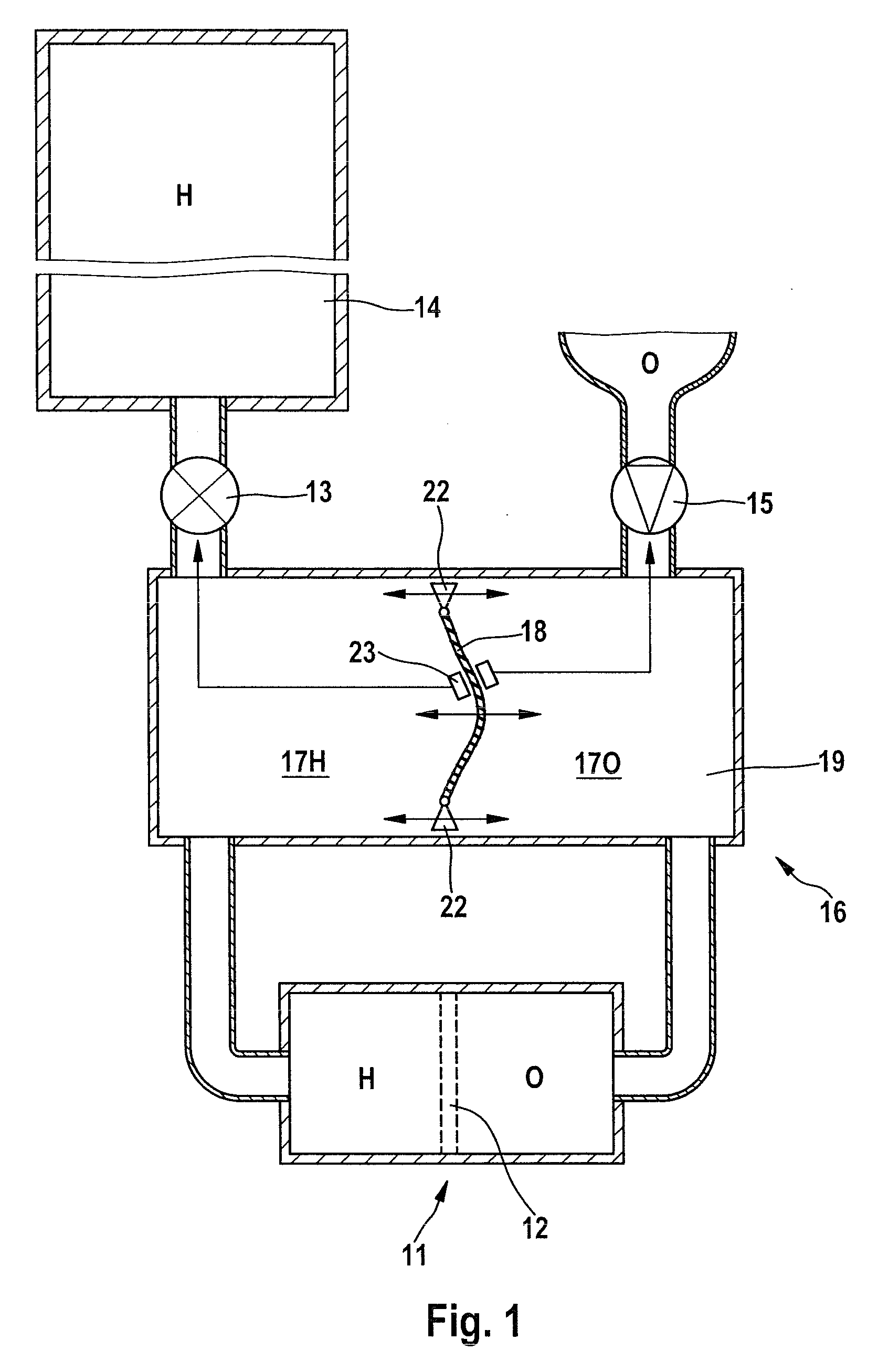
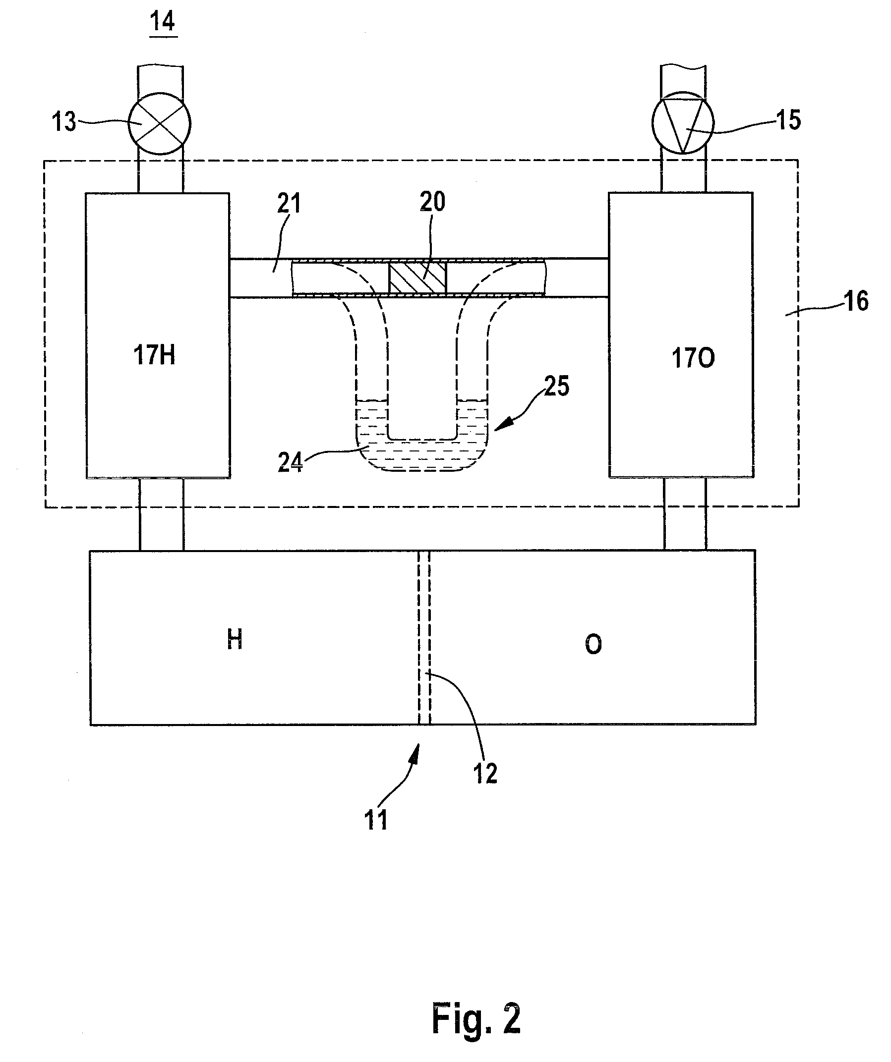
[0021]A fuel cell 11 is split in two by an electrolytic membrane 12. By way of example, on one side of the membrane 12, specifically the anode side, the cell 11 is fed with hydrogen H as fuel via a pressure-reducing valve 13 from a generator or from a reservoir 14 such as a compressed-gas cylinder and, opposite this, that is to say on the cathode side, the cell is fed for example with oxygen O as the oxidant (from a reservoir or) from the surrounding air, which is supplied by means of a compressor 15.

[0022]This raw-material gas feed is now, however, according to the invention no longer provided directly to the fuel cell 11 but via a pressure equalizing system 16, which is connected directly upstream of it, with two pressure equalizing chambers 17H, 17O which, in the case of FIG. 1, are separated from one another in a gas-tight manner by a separating wall 18, which can be deformed by pressure, as a function of the pressure difference, in a similar manner to a membrane, in a pressure-...


PUM

PropertyMeasurementUnit
pressureaaaaaaaaaa
volumeaaaaaaaaaa
steady-state volumeaaaaaaaaaa

Abstract

A pressure equalizing system (16) having two variable volume elements which interact with one another via a separating medium which can be deformed or can be moved as a function of the pressure difference, with a constant total volume, is positioned upstream of a fuel cell (11) in order to feed the fuel cell (11) with its raw-material gases (H, O). A pressure equalizing container (19) can be provided for this purpose, which is subdivided into two chambers (17H, 17O) by a separating wall (18) which can be deformed or can be moved as a function of the pressure difference; alternatively, two chambers (17H, 17O) are connected to one another by an equalizing channel (21) with a solid or liquid separating medium which can be moved therein as a function of the pressure difference. If the raw-material gas pressures are different, the separating medium is moved towards the chamber (17) with the lower gas pressure until a pressure equilibrium is achieved as a consequence of the corresponding change in the volume elements on both sides of the separating medium. In the fuel cell (11) which is fed from the chambers (17), its membrane (12), which is susceptible to fracture, therefore [cut off] no longer has a destruction-critical dynamic pressure difference applied to it, without having to take control measures for this purpose in feed fittings for the raw-material gases.

Description

BACKGROUND OF THE INVENTION[0001]1. Field of the Invention[0002]The invention relates to a device and a method for the operation of a fuel cell with raw-material gases being fed to it on both sides of an electrolytic membrane thereof.[0003]2. Discussion of the Prior Art[0004]By way of example, DE 10 2007 029 596 A1 describes that an electrolyte membrane, which is permeable for protons but is not permeable for electrons, keeps the two raw-material gases, which are fed in continuously, specifically the fuel supplied on the anode side (for example hydrogen) and the oxidant supplied on the cathode side (for example the oxygen contained in the surrounding area) separate from one another in a fuel cell. In particular, the membrane may be in the form of a thin polymer film (in a fuel cell of the PEM type) or in the form of a brittle oxide ceramic (in a fuel cell of the SOFC type).[0005]The invention is based on the discovery that a very thin membrane such as this is highly susceptible to a...

Claims


Application Information

Patent Timeline
Patent Type & Authority Applications(United States)
IPC IPC(8): H01M8/00H01M8/04
CPCY02E60/50H01M8/04104
Inventor KNEPPLE, RONNYBLUMENSTEIN, DIETERSPETH, BERND
Owner DIEHL AEROSPACE GMBH
Why Eureka
Try Eureka