
Device and method for measuring and controlling the speed and torque of a DC motor

a technology of dc motors and control devices, applied in the direction of motor/generator/converter stoppers, dynamo-electric gear control, motor/generator/converter stoppers, etc., can solve the problem of motor velocity oscillation, the speed and torque of the dc motor cannot be measured directly, and the mismatch between calculated and actual flux can arise in the conventional control system, so as to reduce the velocity oscillation and the curve is flexible

Active Publication Date: 2012-06-12
MAGNETEK
View PDF22 Cites 0 Cited by
  • Summary
  • Abstract
  • Description
  • Claims
  • Application Information

AI Technical Summary

Benefits of technology

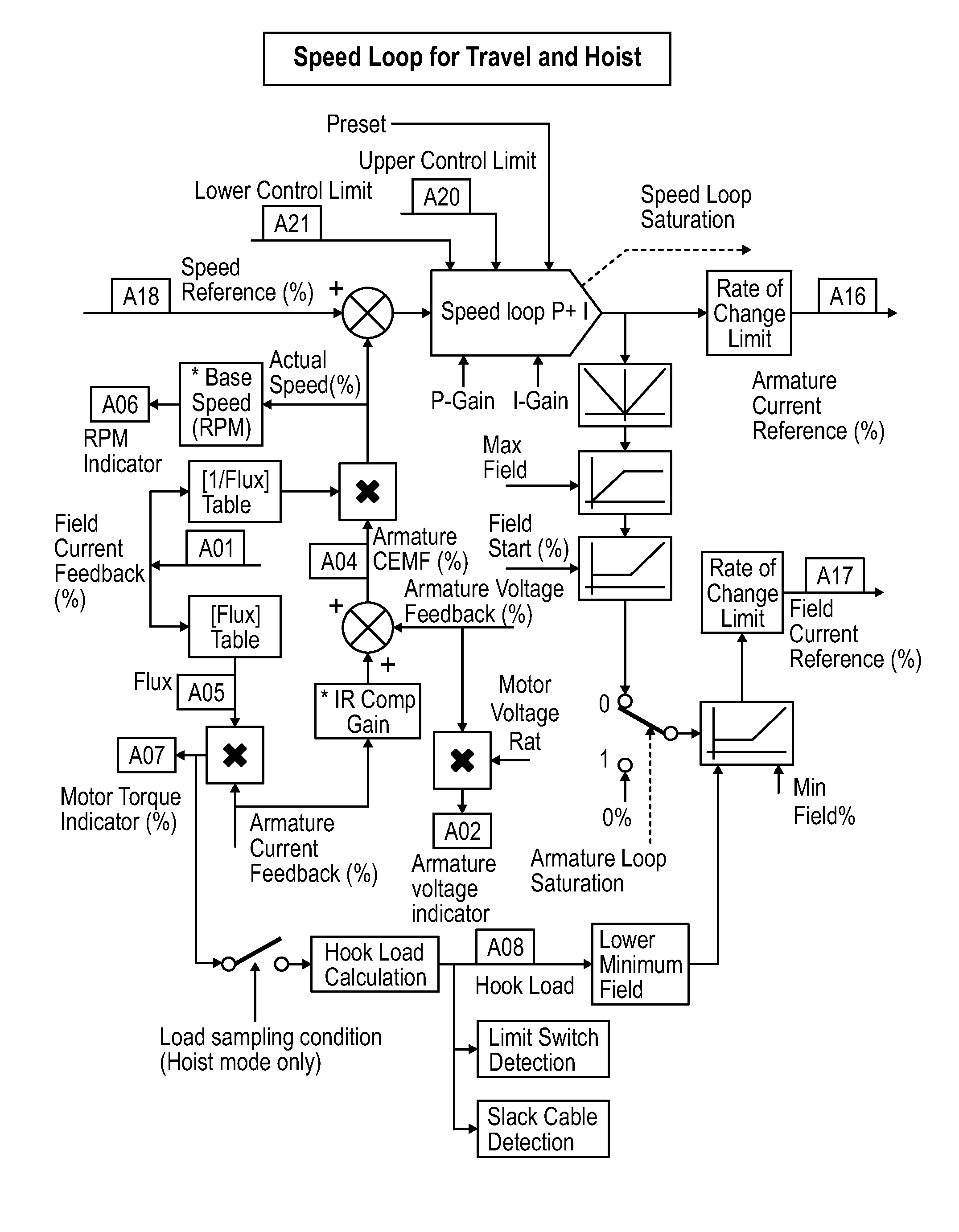
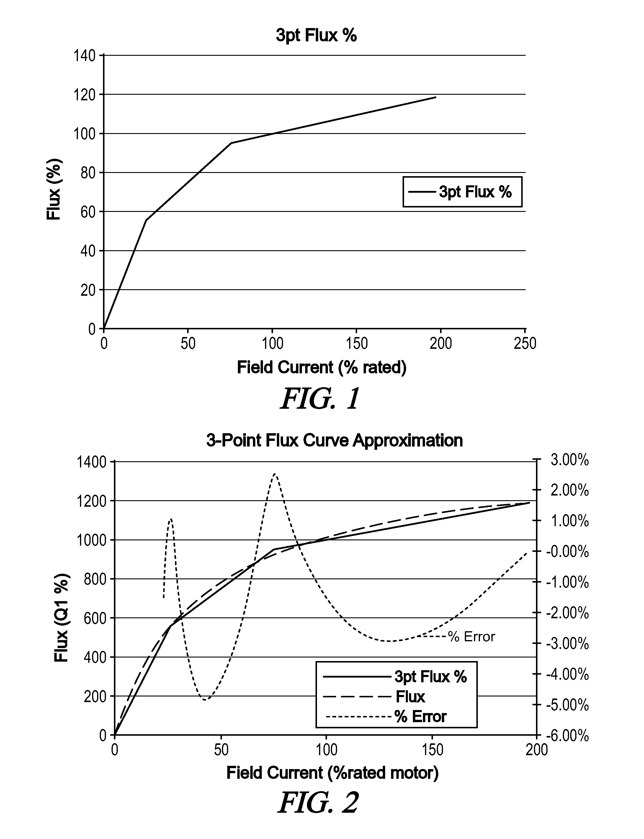
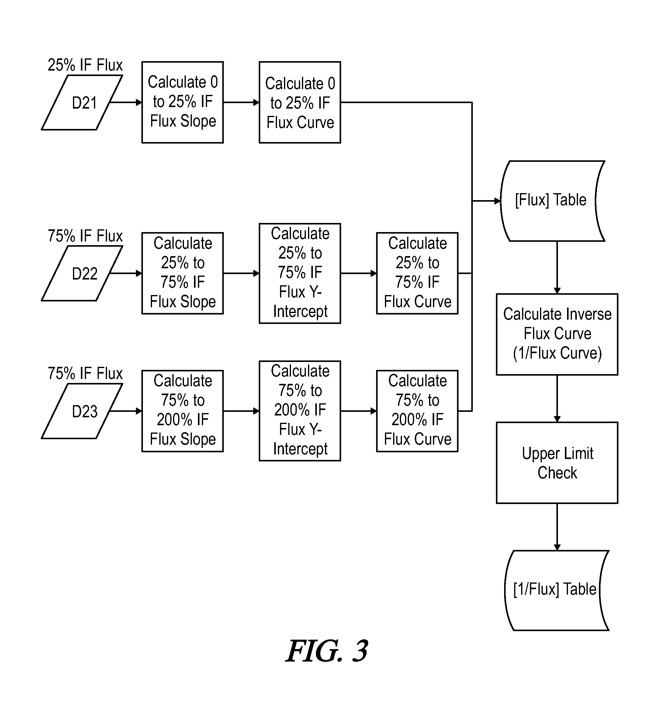
[0009]The present invention minimizes velocity oscillations that occur when DC motor speed is calculated using motor field flux and armature voltage. In accordance with one embodiment of the invention, a flexible flux curve is implemented in the motor control device that is intended to be tuned for each motor in the field. The flux curve is calculated using three user-defined points at 25%, 75% and 200% of rated motor field current. Those three points are used to calculate two flux curve lines. One flux curve line is positioned between 25% and 75% of rated motor field current. The second flux curve line is positioned between 75% and 200% of rated motor field current. Two flux curve lines are used because a typical motor field flux curve exhibits a “knee” at the field saturation point. To make the curve more flexible and to more closely approximate the motor's actual flux curve, the 75% field current can be varied by the user.
[0010]The present invention allows for more accurate calculations of DC motor speed and torque, while accounting for each motor's unique performance characteristics.
[0011]Thus, the present invention uses a flux curve that is flexibly adapted (tuned) for each motor in the field. This flux curve is constructed from user-defined points at different rated field currents (e.g., 25%, 75%, and 200%). These points are then used to calculate two flux curve lines, one between the two lower rated currents and one between the two upper rated currents. This allows the motor control system to perform a more accurate calculation of motor speed and torque, using characteristics of the actual motor being controlled.

Problems solved by technology

Although it is easy to measure the armature voltage in an operating DC motor, motor field flux cannot easily be measured directly.
However, if the flux parameter that is approximated by the control system does not match the actual motor field flux, motor velocity oscillations occur.
This mismatch between calculated and actual flux can arise in a conventional control system because the field current to flux curve is unique for each motor, varying according to time, motor size, and manufacturer.
These unwanted motor velocity oscillations often occur under light motor loads when it is desirable to operate the motor under a weakened field.
If the motor cannot maintain a consistent velocity under weakened field conditions, the end user will not be able to take advantage of the field weakening features.

Method used


Image

  • Device and method for measuring and controlling the speed and torque of a DC motor
  • Device and method for measuring and controlling the speed and torque of a DC motor
  • Device and method for measuring and controlling the speed and torque of a DC motor

Examples


Embodiment Construction

[0019]Referring first to FIGS. 6 and 7, one embodiment of a DC motor control device 10 is shown. The motor control device 10 includes a control module 15 operatively coupled to a driver module 20. The control module 15 and driver module 20 have control inputs that are coupled to a user control and display device 25. The control module 15 conventionally includes a microprocessor, microcontroller, or other logic unit that is programmed to provide motor control commands to the driver module 20 at one or more control outputs. The driver module 20 receives and processes the control commands from the control module 15. In response to the motor control commands, the driver module 20 provides motor control signals at driver outputs 1-6 (FIG. 6).

[0020]As shown on FIG. 6, the driver outputs 1-6 are conventionally coupled to power switch modules Q1, Q2, and Q3 in a motor power circuit 30. The power switch modules Q1, Q2, and Q3 respond to the motor control signals to provide the voltage and cu...


PUM


Abstract

A DC motor control device calculates motor speed using determinations of motor field flux and armature voltage in the motor. The device includes a control module having one or more control inputs and one or more control outputs. At least one control input is configured to receive data representing field current measured in the DC motor. The control module includes flux curve logic that is responsive to measurements of motor field current to calculate a field flux in the motor. The flux curve logic uses a flux curve stored in the control module, the flux curve representing a functional relationship between field current and field flux in the motor. The flux curve is defined by a plurality of flux curve data points corresponding to a plurality of motor field currents within a lower current range and within an upper current range. The flux curve is further defined by at least a first flux curve line positioned within the lower current range and a second flux curve line positioned within the upper current range.

Description

[0001]A portion of the disclosure of this patent document contains material that is subject to copyright protection. The copyright owner has no objection to the reproduction of the patent document or the patent disclosure, as it appears in the U.S. Patent and Trademark Office patent file or records, but otherwise reserves all copyright rights whatsoever.CROSS-REFERENCES TO RELATED APPLICATIONS[0002]This application claims benefit of the following patent application(s) which is / are hereby incorporated by reference: NoneSTATEMENT REGARDING FEDERALLY SPONSORED RESEARCH OR DEVELOPMENT[0003]Not ApplicableREFERENCE TO SEQUENCE LISTING OR COMPUTER PROGRAM LISTING APPENDIX[0004]Not ApplicableBACKGROUND OF THE INVENTION[0005]The present invention generally relates to DC motor control devices and methods. More particularly, the present invention pertains to devices and methods for controlling a DC motor in which motor speed is calculated using motor field flux and armature voltage parameters....

Claims


Application Information

Patent Timeline
IPC IPC(8): H02P1/00H02P7/00
CPCH02P7/282H02P7/2985
Inventor WELLNITZ, JASON
Owner MAGNETEK
Learn More