
Rock physics model for simulating seismic response in layered fractured rocks

a layered fractured rock and seismic response technology, applied in seismology for waterlogging, instruments, analogue processes, etc., can solve the problems of inability to apply real-time applications, models with limitations are hardly useful, and inclusion-based effective medium theories (e.g. dem and sc) have their own problems

Active Publication Date: 2012-05-22
EXXONMOBIL UPSTREAM RES CO
View PDF31 Cites 22 Cited by
  • Summary
  • Abstract
  • Description
  • Claims
  • Application Information

AI Technical Summary

Benefits of technology

[0029](d) optimizing the three anisotropy parameters by minimizing errors between calculated and measured values of P-wave and cross-dipole (fast and slow) S-wave logs, said calculated P-wave and cross-dipole (fast and slow) S-wave logs being calculated using the elastic constants, which are then modified in performing the optimizing.

Problems solved by technology

Existing theories and workflows for modeling anisotropic elastic properties of a fractured rock are often of limited usefulness.
This is called the dilute pore concentration assumption and models with this limitation are hardly useful in real applications.
However, inclusion-based effectively medium theories (e.g. DEM and SC) have their own problems.
First, one key assumption in these models is that all pores or fractures are isolated, which does not allow the fluid communication between fractures and matrix pores.
Therefore these models are not suitable to simulate low-frequency seismic responses.
Another drawback with the DEM or SC theory is that they are computationally extremely expensive.
In some cases, it becomes impractical to apply their anisotropic versions, for example, to well log analysis.
They are unable to handle rock columns with mixed anisotropy types (e.g. shale anisotropy and layering anisotropy mixed with fracture anisotropy).
If the overall thickness of the mixed rock column is less than, for example, half of the wavelength, it is not possible to separate the fracture anisotropy from shale anisotropy and layering anisotropy.
However, the method is unable to handle a geological system with types of anisotropy other than VTI.

Method used


Image

  • Rock physics model for simulating seismic response in layered fractured rocks
  • Rock physics model for simulating seismic response in layered fractured rocks
  • Rock physics model for simulating seismic response in layered fractured rocks

Examples


examples

[0131]The integrated workflow and the rock physics model of the present invention were used to study the effect of fractures on seismic response at an East Texas well. Two examples showing that the present invention generates suitable elastic constants are presented here. In the first example, a single fracture set is assumed, aligned perpendicular to the x-axis, in a mixed carbonate-clastic environment (see track 71 of FIG. 7, where the shale volume fraction varies greatly with depth). The fracture porosity (track 72) is zero above 3800 ft, where all the calculated anisotropy comes from shale anisotropy. (In tracks 73-75, blue curves are C11, red curves are C22, and green curves are C33.) Thus, C11 and C22, the two quantities plotted on track 73, are the same above 3800 ft. Below 3800 ft, the anisotropy is HTI in clean limestone and VTI in pure shale, and orthorhombic in shaly (muddy) carbonate with vertical fractures. Azimual anisotropy is indicated by the difference between C11 a...


PUM


Abstract

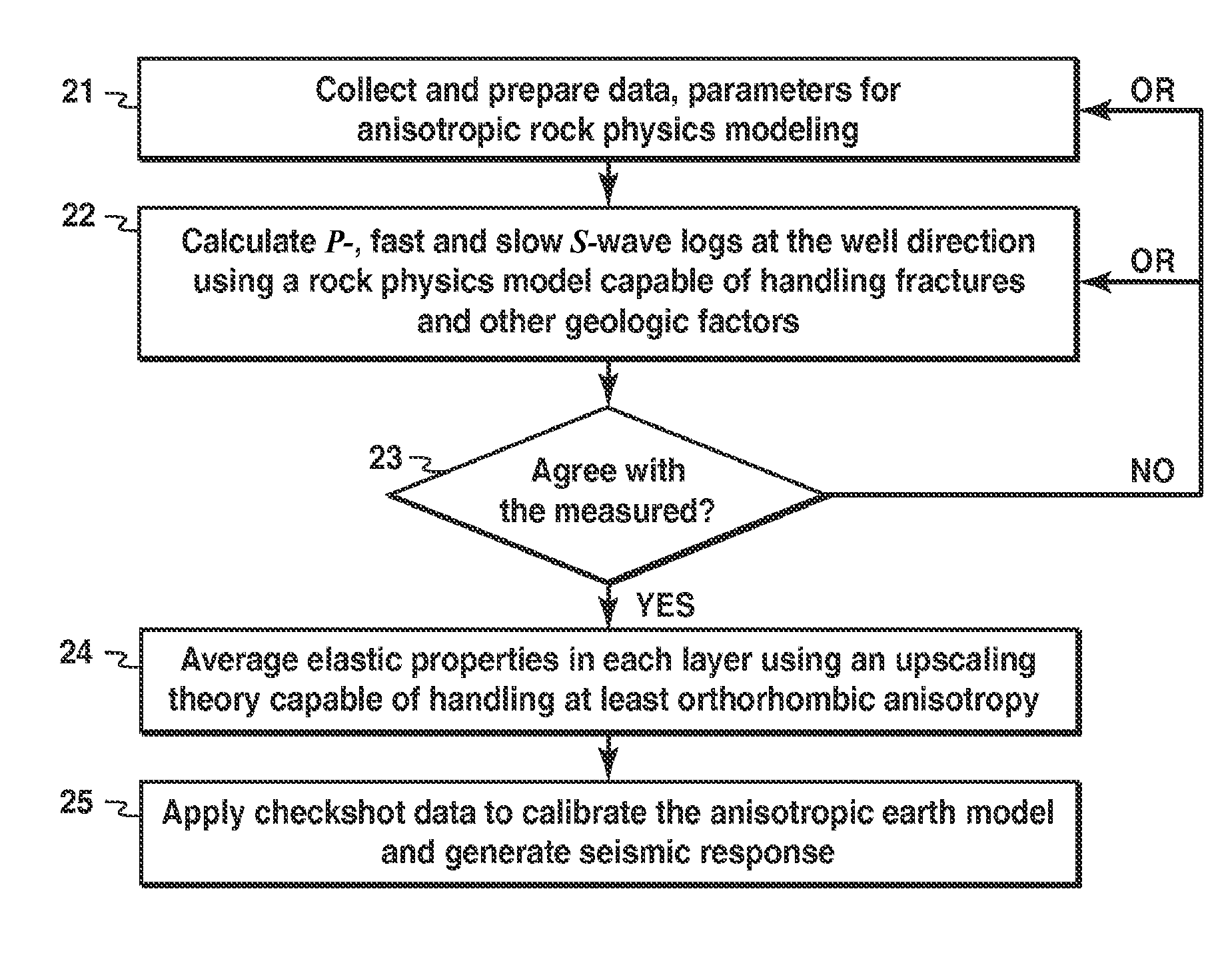
Method for modeling anisotropic elastic properties of a subsurface region comprising mixed fractured rocks and other geological bodies. P-wave and fast and slow S-wave logs are obtained, and an anisotropic rock physics model of the subsurface region is developed (21). P- and fast and slow S-wave logs at the well direction are calculated using a rock physics model capable of handling fractures and other geological factors (22). Calculated values are compared to measured values in an iterative model updating process (23). An upscaled ID model is developed by averaging elastic properties in each layer using an upscaling theory capable of handling at least orthorhombic anisotropy (24). The ID model may be used to generate synthetic seismic response for well ties or AVO modeling (25). Further, a method is disclosed for estimating anisotropy parameters from P- and fast / slow S-wave logs from one or more deviated wells.

Description

CROSS-REFERENCE TO RELATED APPLICATION[0001]This application is the National Stage of International Application No. PCT / US2009 / 032007, which published as WO 2009 / 108432, filed 1 Jan. 2009, which claims the benefit of U.S. Provisional Application No. 61 / 067,534, filed 28 Feb. 2008, each of which is incorporated herein by reference, in its entirety, for all purposes.BACKGROUND OF THE INVENTION[0002]1. Field of the Invention[0003]This invention relates generally to the field of petroleum reservoir management or other fields where movement of pore fluids through fractured rock is important, and more particularly to seismic fracture characterization methods. Specifically, the invention is a method for developing a rock physics model for layered fractured rocks to use in simulating seismic response.[0004]2. Background of the Invention[0005]Fractures may serve as major conduits for movement of pore fluids (hydrocarbons or water) and dissolved chemicals through low porosity, low permeabilit...

Claims


Application Information

Patent Timeline
Patent Type & Authority Patents(United States)
IPC IPC(8): G01V1/00G06F7/60G06F17/10
CPCG01V1/50G01V2210/626
Inventor XU, SHIYUCHEN, GANGLIN
Owner EXXONMOBIL UPSTREAM RES CO
Learn More