
Head-of-wall fireblocks and related wall assemblies

a technology of head-of-wall joints and fireblocks, which is applied in the direction of fireproofing, heat-proofing, walls, etc., can solve the problems of low efficiency, low cost, and high labor intensity of head-of-wall joints, and achieves the effects of reducing or preventing, reducing the number of products and methods available, and improving the safety of workers

Inactive Publication Date: 2012-05-22
KLEIN JAMES ALAN
View PDF28 Cites 85 Cited by
  • Summary
  • Abstract
  • Description
  • Claims
  • Application Information

AI Technical Summary

Benefits of technology

The fireblock device efficiently seals head-of-wall construction joints, passing 2-hour fire and hose stream tests, demonstrating effective smoke and fire containment while accommodating ceiling deflections, thus enhancing fire protection in dynamic head-of-wall systems.

Problems solved by technology

Head-of-wall joints often present a serious challenge in terms of reducing or preventing the spread of smoke and fire during a building fire.
All of these approaches, however, are relatively labor intensive and thus expensive.
Thus, and although construction joints and gaps are generally sealed in some manner (e.g., mineral wool and / or elastomeric coatings), there are few products and methods available for effectively and efficiently sealing head-of-wall construction joints and gaps (to thereby significantly enhance the ability of such joints and gaps to withstand smoke and fire penetration).
In particular, there are very few products and methods available that address the needs for adequate fire protection sealing of dynamic head-of-wall systems associated with steel stud wall constructions.

Method used


Image

  • Head-of-wall fireblocks and related wall assemblies
  • Head-of-wall fireblocks and related wall assemblies
  • Head-of-wall fireblocks and related wall assemblies

Examples


example

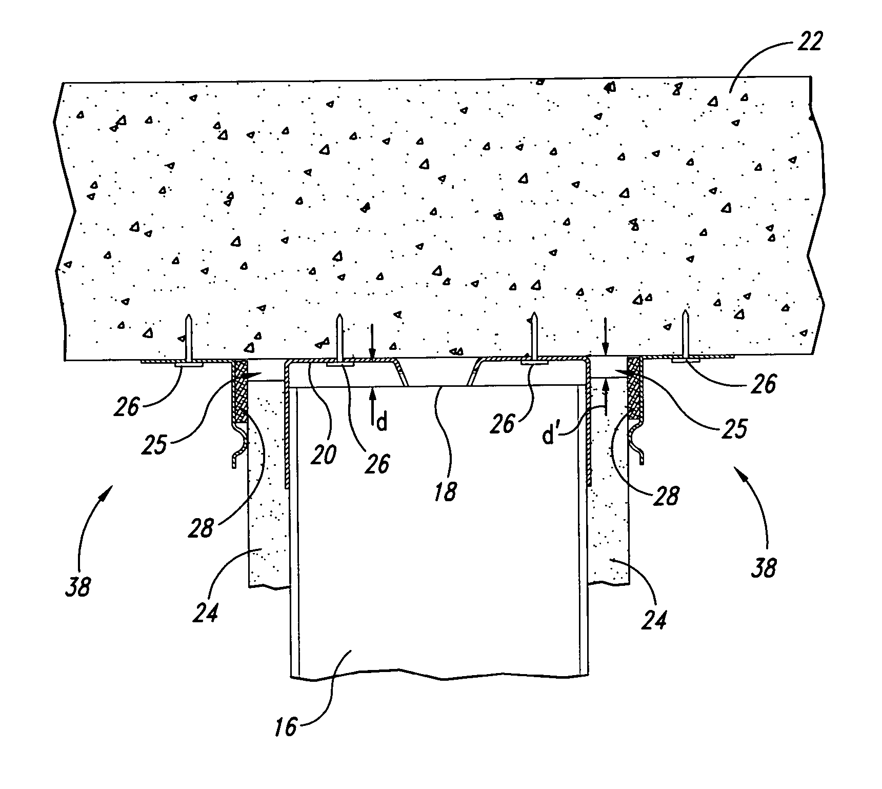
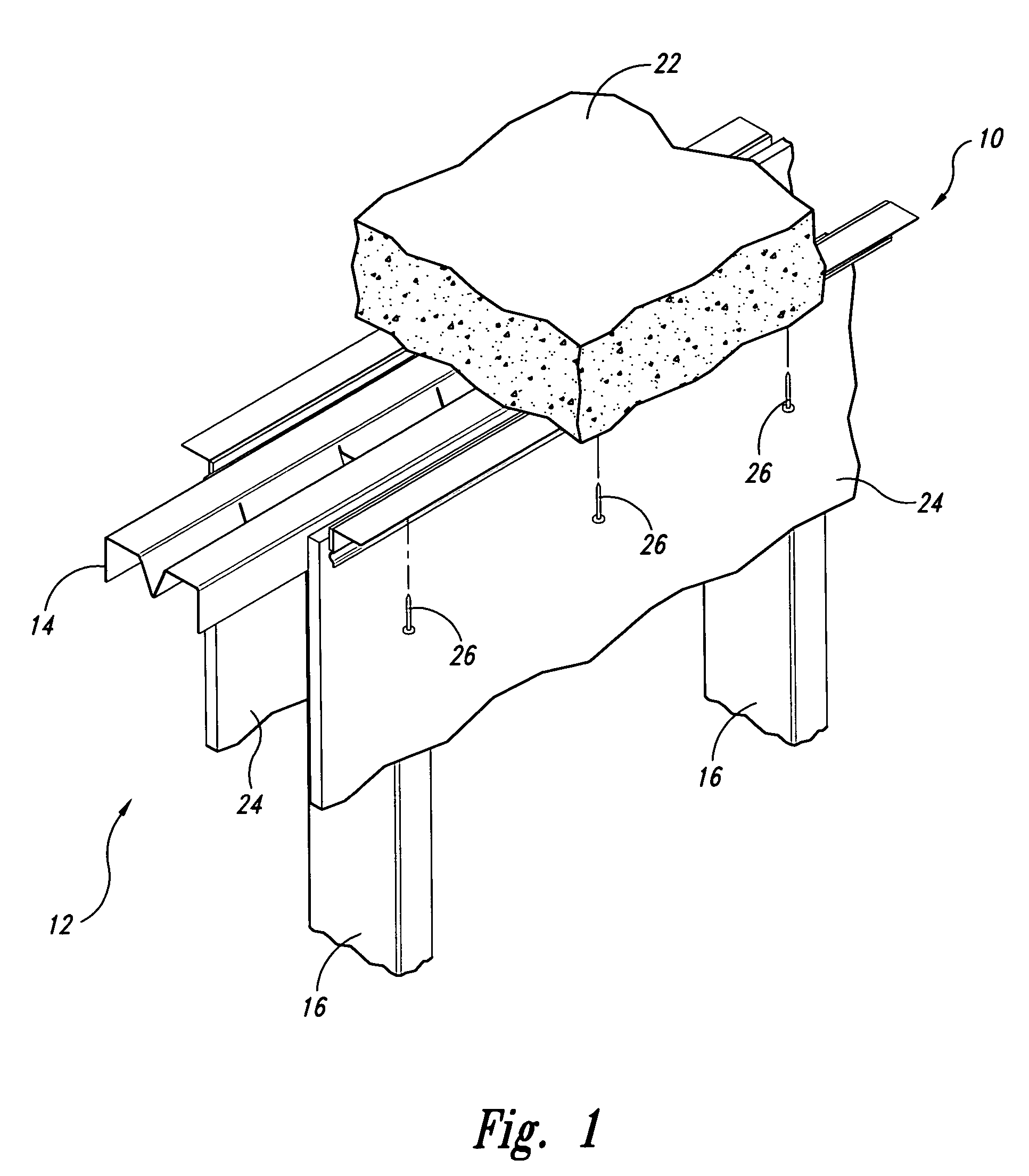
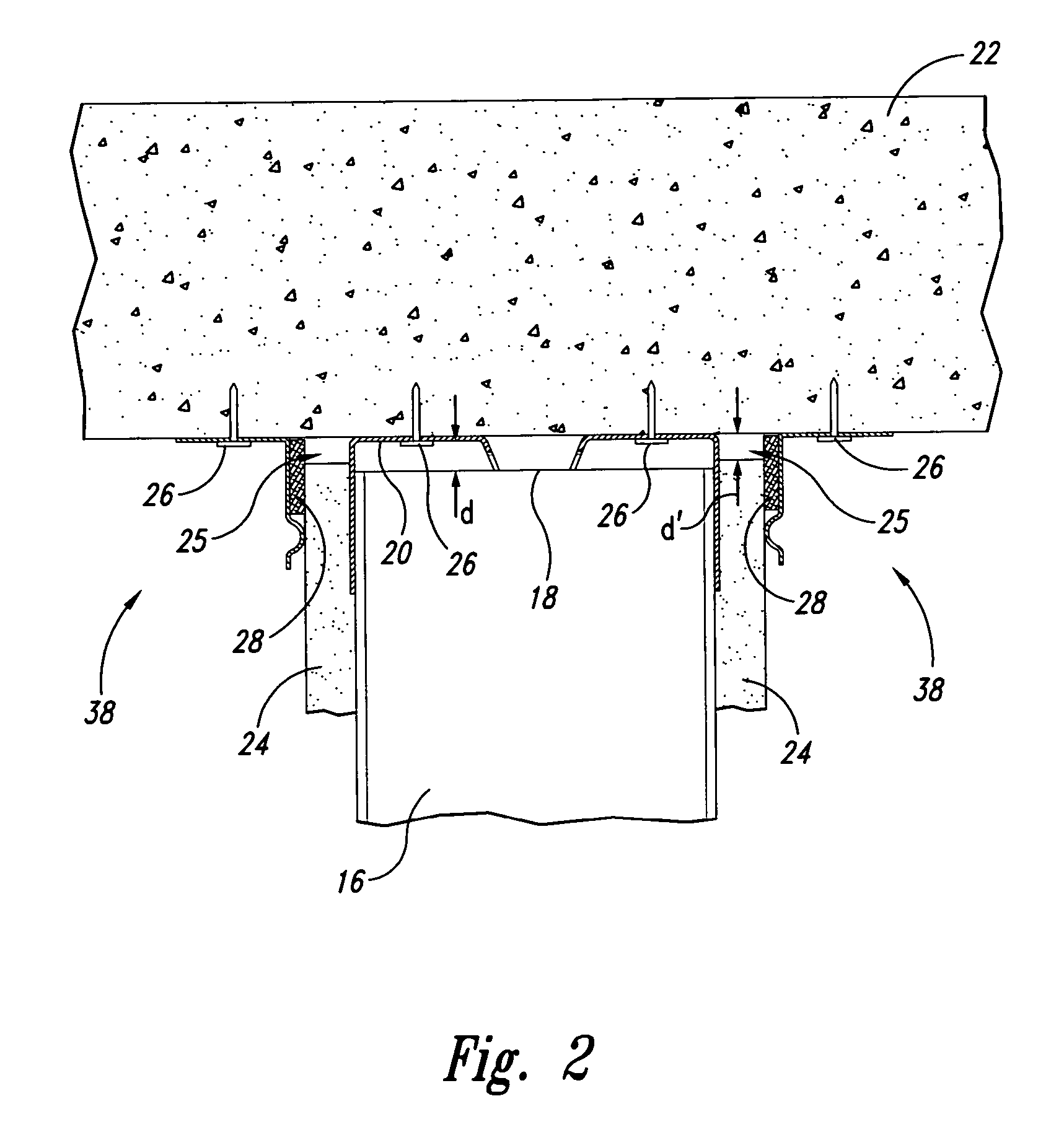
[0029]From Jul. 20 to Jul. 26, 2005, a series of head-of-wall joint firestop system tests were conducted to evaluate the effectiveness of the fireblock device generally shown in FIGS. 1-5 in combination with a dynamic head-of-wall assembly also generally shown in FIGS. 1-3, and 5. The test were conducted in accordance with UL 2079, “Tests for Fire Resistance of Building Joint Systems” (also known as the 2-hour fire and hose stream test). In the tests, the joint length was approximately 1 meter and the joint movement or deflection was approximately 1 inch. The dynamic head-of-wall assembly was cycled or deflected 500 times at about 10 cycles per minute and was then fire tested at maximum extension. The fireblock device in combination with a dynamic head-of-wall assembly readily passed the 2-hour fire and hose stream test, both when the ceiling was a concrete slab as shown in FIGS. 1-3 and when the ceiling was a fluted roof deck as shown in FIG. 5.


PUM


Abstract

Fireblock devices, wall assemblies and related methods useful for retarding the spread of smoke and fire through dynamic head-of-wall construction joints and gaps are disclosed herein. In one embodiment, the fireblock device is characterized by an elongated angled channel member having an elongated intumescent material strip, wherein the angled channel member is defined by an elongated top flange member connected to an elongated side flange member along a lengthwise edge, and wherein the top and side flange members define a right angle and a lengthwise interior corner region, and wherein the top and side flange members each have inner flange member surfaces that face inwardly with respect to the interior corner region, and outer flange member surfaces that face outwardly with respect to the interior corner region, and wherein the intumescent material strip is affixed on the outer flange member surface of the side flange member.

Description

CROSS-REFERENCE TO RELATED APPLICATION[0001]This application claims the benefit of U.S. Provisional Application No. 60 / 637,379 filed on Dec. 20, 2004, which application is incorporated herein by reference in its entirety for all purposes.TECHNICAL FIELD[0002]The present invention relates generally to fire blocking and containment systems used in the construction of buildings and, more particularly, to fireblocks used to seal head-of-wall construction joints and gaps.BACKGROUND OF THE INVENTION[0003]As is appreciated by those skilled in the art of building construction, a head-of-wall joint (also sometimes referred to as a top-of-wall joint) refers to the junction or interface existing between a building wall and the ceiling (where the ceiling may also be a floor or corrugated pan roof deck, for example). Head-of-wall joints often present a serious challenge in terms of reducing or preventing the spread of smoke and fire during a building fire. In this regard and in common practice, ...

Claims


Application Information

Patent Timeline
Patent Type & Authority Patents(United States)
IPC IPC(8): E04B1/94E04B1/88
CPCE04B2/7411
Inventor KLEIN, JAMES ALAN
Owner KLEIN JAMES ALAN
Learn More