Heart valve prosthesis

a heart valve and prosthesis technology, applied in the field of heart valve prosthesis, can solve the problems of coagulation cascade, tissue leaflets not being fully closed or opened, damage to blood elements,

Inactive Publication Date: 2004-02-12
MEDTRONIC INC
View PDF36 Cites 325 Cited by
  • Summary
  • Abstract
  • Description
  • Claims
  • Application Information

AI Technical Summary

Problems solved by technology

The opening and closing of mechanical heart valve occluders can damage blood elements and trigger a coagulent cascade.
However, tissue leaflets can become calcified over time distorting the leaflet shape and ultimately leading to failure of the tissue leaflets to fully close or open.
However, calcification and tear issues of polymeric materials remain to be solved before a polymeric valve can be realized.)
However, none of the current available tissue valves allows a surgeon to rotate the stent within the suturing ring because the suturing ring is an integral part of the stent.
Any attempt to do so by cutting the suturing ring assembly apart where the split ends abut one another would effectively destroy the suturing ring.
Moreover, it would not be possible to locate the split ends beneath the fabric without disassembling the fabric as well as the cord or band.
Despite improvements in longevity, adverse reactions and complications with implanted mechanical heart valves and tissue valves of the types described above requiring surgical replacement can occur from time-to-time during the lifetime of a patient.
Removal of the existing sutures to remove the suturing ring and restitching of a new suture ring in place can compromise the integrity of the valvar rim and lead to further recovery complications, morbidity and mortality.
This approach requires a valve design that can be stitched in place in the suturing ring annulus, does not allow the tissue valve to be easily rotated in the suturing ring in the manner described above, and requires considerable care and time to execute.
While this approach would appear to be very beneficial, it has not been established that the temperature induced shape changes are robust enough to assure retention of the tissue or mechanical valve or large enough when cooled by cooling fluid to expand a chronically implanted suturing ring to allow removal of a valve body or stent.
Moreover, this concept is impractical because of high cost and difficulty in fabrication.
Consequently, none of these proposed interlocking mechanisms have been adopted.
Tissue ingrowth into the interstices of the suturing ring fabric occurs in time, and the sutures may become unnecessary to retain the suturing ring in place.

Method used


Image

  • Heart valve prosthesis
  • Heart valve prosthesis
  • Heart valve prosthesis

Examples


Embodiment Construction

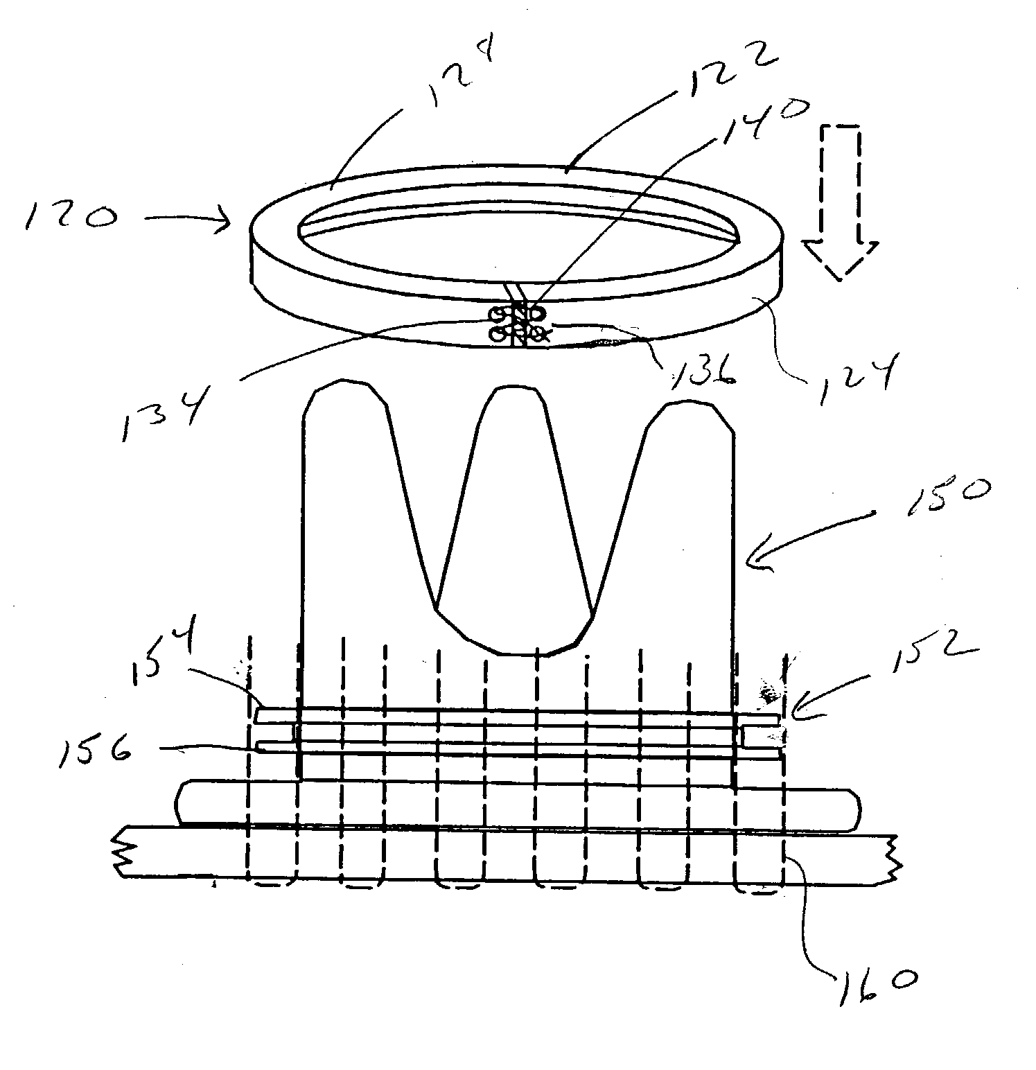
[0083] The present invention can be implemented to improve implantation procedures and performance of a wide variety of heart valve prostheses of the various types currently existing or that may come into existence that are surgically attached to a prepared valvar rim. As noted above, the present invention involves improved suturing rings that support removable heart valve mechanisms, e.g., tissue valves and mechanical heart valves comprising a heart valve frame and occluder. The valve frames described in the exemplary embodiments are a tissue valve stent or a mechanical valve body, and the occluders include tissue leaflets of a tissue valve or pivotal disk or leaflets of a mechanical heart valve. The various aspects of the present invention may be utilized in attaching any such valve frame or any other valve frames that are devised in the future to a suturing ring.

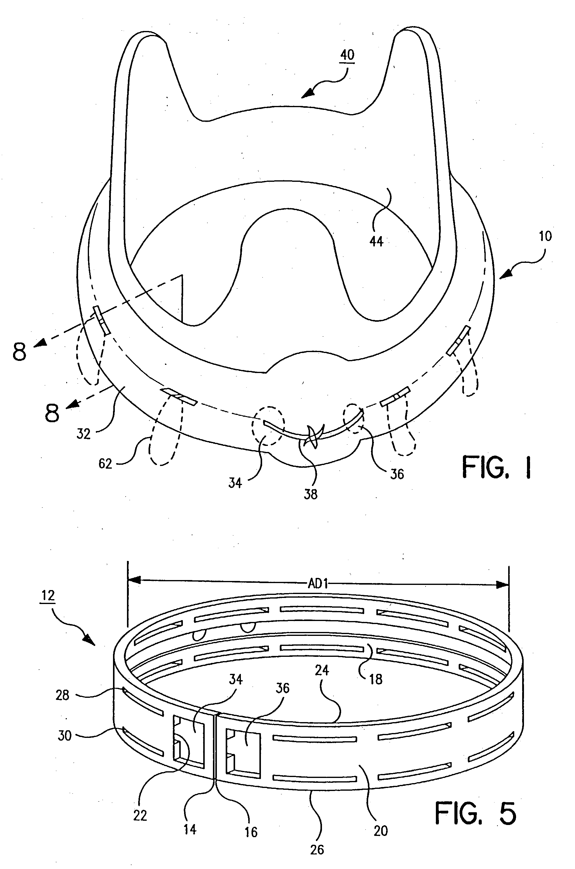
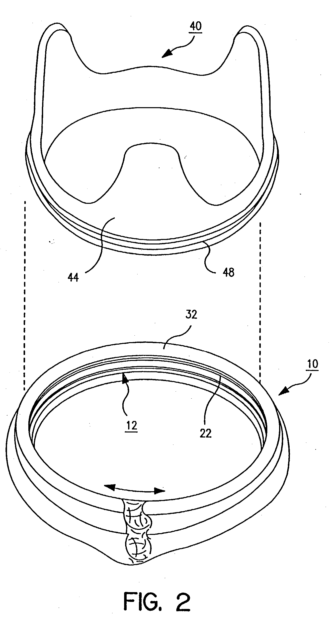
[0084] Thus, for example, FIGS. 1-3 depict a suturing ring 10 that is employed to support a fabric covered stent 40 of ...


PUM


Abstract

A heart valve prosthesis has a frame that includes at least one outwardly extending annular flange adjacent to a suturing ring and a band comprising an inwardly extending annular flange that is capable of engagement with the annular flange of the frame. A tortuous path is formed between the annular flange of the frame and the annular flange of the band that can engage and restrain a suture placed between them. One or more split portions or tab portions on the band are adapted to lock the band in engagement with the flange of the frame. Such a device can be used to more easily replace a heart valve by advancing a sutures through a suturing ring on the valve and the valvular rim such that they are brought outward of the flange extending from the frame and then advancing the band over the valve and over the sutures at a proximal, outflow end of the valve until the band engages the flange and captures the sutures between the band and the flange.

Description

[0001] This application is a continuation-in-part of Ser. No. 10 / 196,527 filed Jul. 16, 2002, which is incorporated by reference herein in its entirety.[0002] This invention relates generally to implantable heart valve prostheses, particularly to improvements in a heart valve prosthesis facilitating initial implantation of the suturing ring and replacement of a chronically implanted heart valve mechanism supported by the suturing ring providing enhanced durability reliability, ease of use, and ease of manufacture.[0003] Implantable heart valve prostheses have been used to replace various diseased or damaged natural aortic valves, mitral valves, pulmonic valves and tricuspid valves of the heart. The aortic and mitral valves are most frequently replaced due to heart disease, congenital defects or injury. The mitral valve controls the flow of blood between the left atrium and the left ventricle and the aortic valve controls the blood flow from the left ventricle into the aorta. General...

Claims


Application Information

Patent Timeline
Patent Type & Authority Applications(United States)
IPC IPC(8): A61F2/24
CPCA61F2/2409A61F2/2412A61F2/2415A61F2220/0075A61F2250/001A61F2250/006A61F2220/0016A61F2/2418
Inventor SHU, MARK C.S.
Owner MEDTRONIC INC
Why Eureka
Try Eureka