
Method for manufacturing a flanged element and a flanged element

Active Publication Date: 2012-05-08
VERAX ENG
View PDF11 Cites 2 Cited by
  • Summary
  • Abstract
  • Description
  • Claims
  • Application Information

AI Technical Summary

Benefits of technology

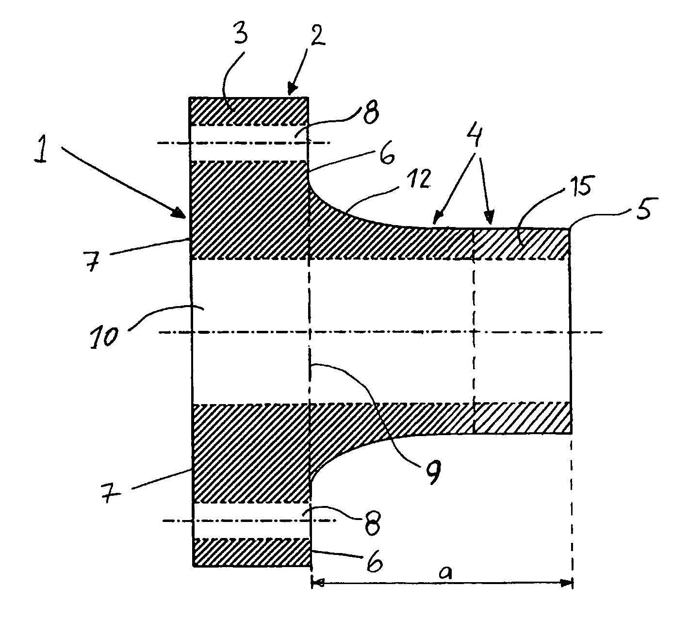
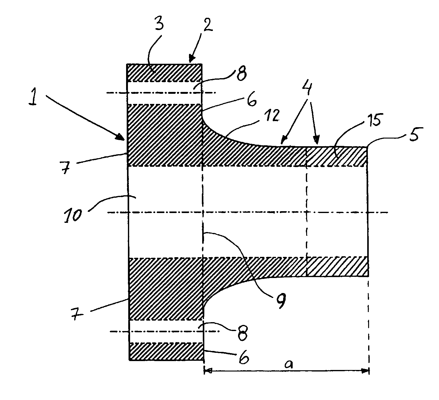
[0007]In practice, this means that the pipe part of the flanged member is made substantially longer than what is the standard practice, which leads to the advantageous result that, when the extended end of the pipe part is being welded to the pipe system, the heat transfer that results from the welding will not cause any substantial deformation of the contact surface of the flange. Thus, due to the extended pipe part, a substantial part, if not all, of the heat generated will be absorbed by the extended pipe part, such that the heat transferred to the end surface of the flange becomes drastically reduced. Another advantageous effect of the extended pipe part is that it will have a stiffening effect on the structure, which also contributes to considerable reduction of the peril of deforming of the end surface of the flange.
[0010]According to another advantageous embodiment, at least part of the pipe part is manufactured as a separate part, which is attached to the rest of the flanged member before final machining of the front end surface of the flange part. This has the advantage of ensuring flexibility in the manufacture. The separate extension part can be joined to the flanged member by welding, for example, which in itself may be expected to result in deformation of the contact surface. By making such an extension, according to the above invention, before the final machining of the contact surface of the flange end, i.e. the end surface, any possible deformation of the contact surface will become corrected during the final machining operation, which also offers a substantial benefit.

Problems solved by technology

Regarding large size pipe, as for an example with applications within the offshore-, subsea-, process- and petroleum-industries and also in nuclear power plants, flanged joints and flanged members of traditional design, are characterised by considerable weight, large bulk and high cost.
This problem is also common with small size flanges, having a rather small mass relative to the pipe shaped part of the flange member, and which therefore heat up rapidly.
It is readily understood, that this circumstance does impair the performance of the joint tightness, which in many applications creates a most serious problem.
Even a defect in the tightness that results in a very small leakage may, for instance, create a serious peril in cases when substances, which may endanger the environment, are transported in the pipe system.

Method used


Image

  • Method for manufacturing a flanged element and a flanged element
  • Method for manufacturing a flanged element and a flanged element

Examples


Embodiment Construction

[0015]The flanged member 1, illustrated in FIG. 1, displays one end provided with a flange 3 or ring-shaped collar, and forming a flange part 2, and a non-flanged end 5 forming a pipe part 4. The flange part 2 has a front end surface or contact surface 7, intended for abutting against a corresponding surface of a pipe element, of a similar flanged member, or of some other type of component constituting a part of a pipe system. The flange part 2 also has a rear end surface 6 that is essentially plane and, in the illustrated case, principally at a right angle relative to the centre axis of symmetry of the flanged member. The flange 3 has through-bores 8 such that at assembly, the flanged member is bolted together with another flanged member or component, by means of bolts inserted in said bores. Normally there are a number of bores, equally spaced around the flange. All the way through the centre of the flanged member, there is a cylindrical duct 10.

[0016]The flanged member is normall...


PUM

PropertyMeasurementUnit
Fractionaaaaaaaaaa
Fractionaaaaaaaaaa
Fractionaaaaaaaaaa

Abstract

A flanged member for a pipe system, and a method of manufacturing same. The flanged member has a radially projecting flange part and a pipe part. The flange part has a front end surface connects to another flange part, and a radially planar rear end surface facing the pipe part which delimits the rear end of the flange part against the pipe part, together with a radially inward extension of the rear end surface. The pipe part has a free end, adapted to be welded into the pipe system. Before final machining of the front surface of the flange part, the pipe part has an axial length such that its mass is at least 35% of the mass of the flange part so that upon welding of the free end of the pipe part, there is substantially no distortion of the rear surface of the flange part.

Description

BACKGROUND OF THE INVENTION[0001]The present invention relates to a method for the manufacture of a flanged member for a pipe system and to a flanged member intended for use in a pipe system.[0002]It has been known for a long time to join various parts and components for pressure equipment, especially in pipe systems, by using flanged members, usually called flanged pipe joints. By flanged member, also named flange member or merely flange, is here intended a pipe element having a ring-shaped collar or flange at one of its ends. So-called flanged pipe joints include two flanged members that are bolted together, and they are used, for instance, for the joining of pipes in numerous applications. A flanged member is then attached to one end of a pipe, usually by welding. Also an opposite piece of pipe is provided with a flanged member, and the flanged pipe joint is achieved by bolting those two flanged members together. Flanged members are also used for the connection of a piece of pipe...

Claims


Application Information

Patent Timeline
IPC IPC(8): F16L23/00F16L23/032
CPCF16L23/032Y10T29/49995
Inventor WEBJORN, MATS
Owner VERAX ENG
Learn More