
Liquid crystal display

a liquid crystal display and display technology, applied in non-linear optics, instruments, optics, etc., can solve the problems of reducing the effective aperture ratio, and consuming relatively little power, so as to reduce the texture and increase the effective aperture ratio

Active Publication Date: 2012-05-01
SAMSUNG DISPLAY CO LTD
View PDF10 Cites 8 Cited by
  • Summary
  • Abstract
  • Description
  • Claims
  • Application Information

AI Technical Summary

Benefits of technology

The present invention provides LCDs that control the liquid crystal orientation in regions around pixels to suppress texture and increase the effective aperture ratio. This is achieved by forming a gate line, a common electrode, a first insulating film, a data line, a second insulating film, a pixel electrode, a shielding electrode, a second insulating substrate, and a liquid crystal layer. The technical effects include improved image quality and reduced power consumption.

Problems solved by technology

LCDs can be easily made thin and can consume relatively little power and generate hardly any electromagnetic emission dangerous to humans.
However, their lateral visibility is poorer than front visibility.
However, PVA mode LCDs frequently exhibit texture or afterimages and are limited with regard to a wide viewing angle.
However, in a PLS mode LCD, the liquid crystal orientation in a region around a pixel cannot be controlled due to the lateral field associated with the data line.

Method used


Image

  • Liquid crystal display
  • Liquid crystal display
  • Liquid crystal display

Examples


Embodiment Construction

[0021]The embodiments described in this section are provided for illustration and do not limit the invention.

[0022]It will be understood that when an element or layer is referred to as being “on” another element, then intervening elements may be present. In contrast, when an element is referred to as being “directly on” another element, then there are no intervening elements. Like numbers refer to like elements throughout. As used herein, the term “and / or” includes any and all combinations of one or more of the associated listed items.

[0023]Spatially relative terms such as “below,”“beneath”, “lower”, “above”, “upper”, and the like, may be used herein to describe relationships between different elements as illustrated in the figures. The invention is not limited however to the spacial orientation depicted in the figures.

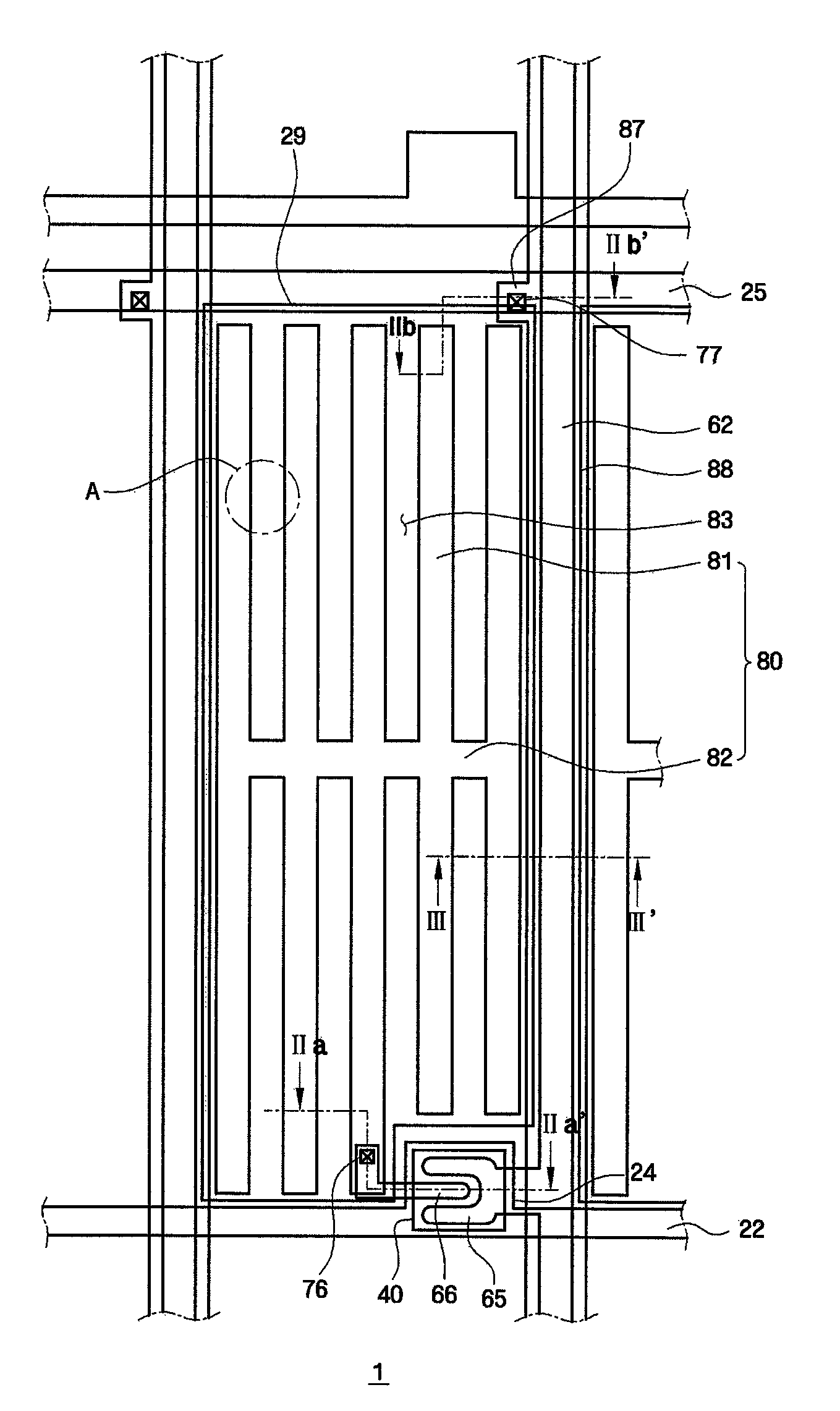
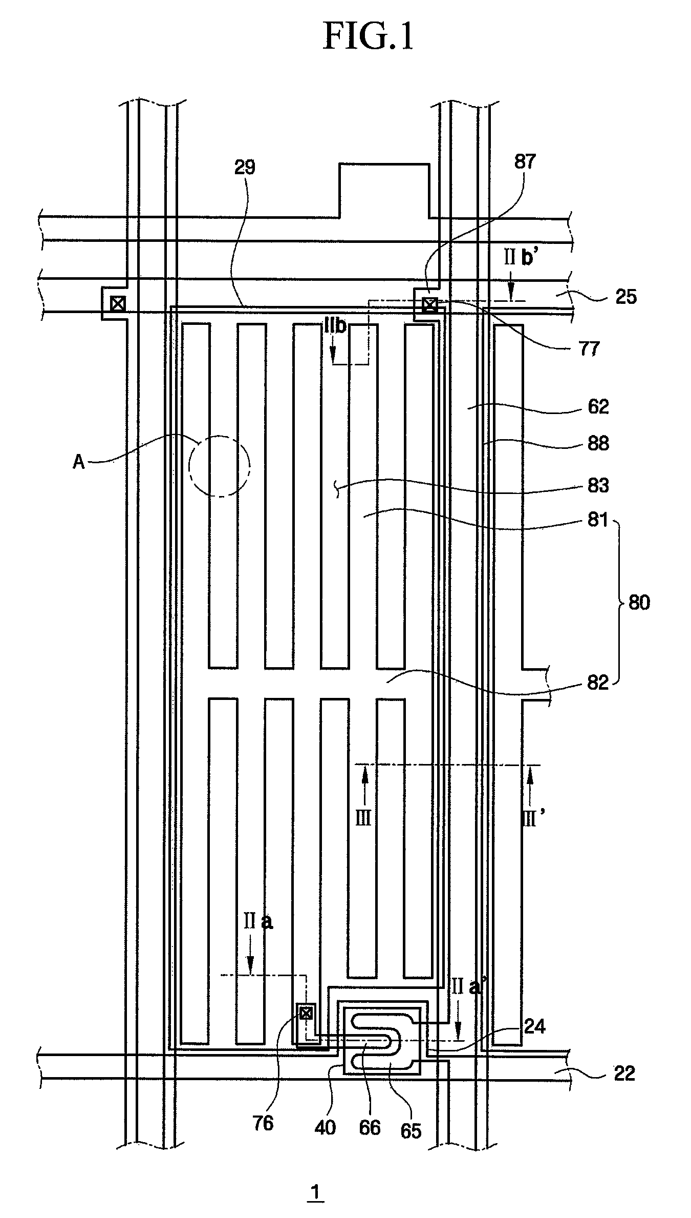
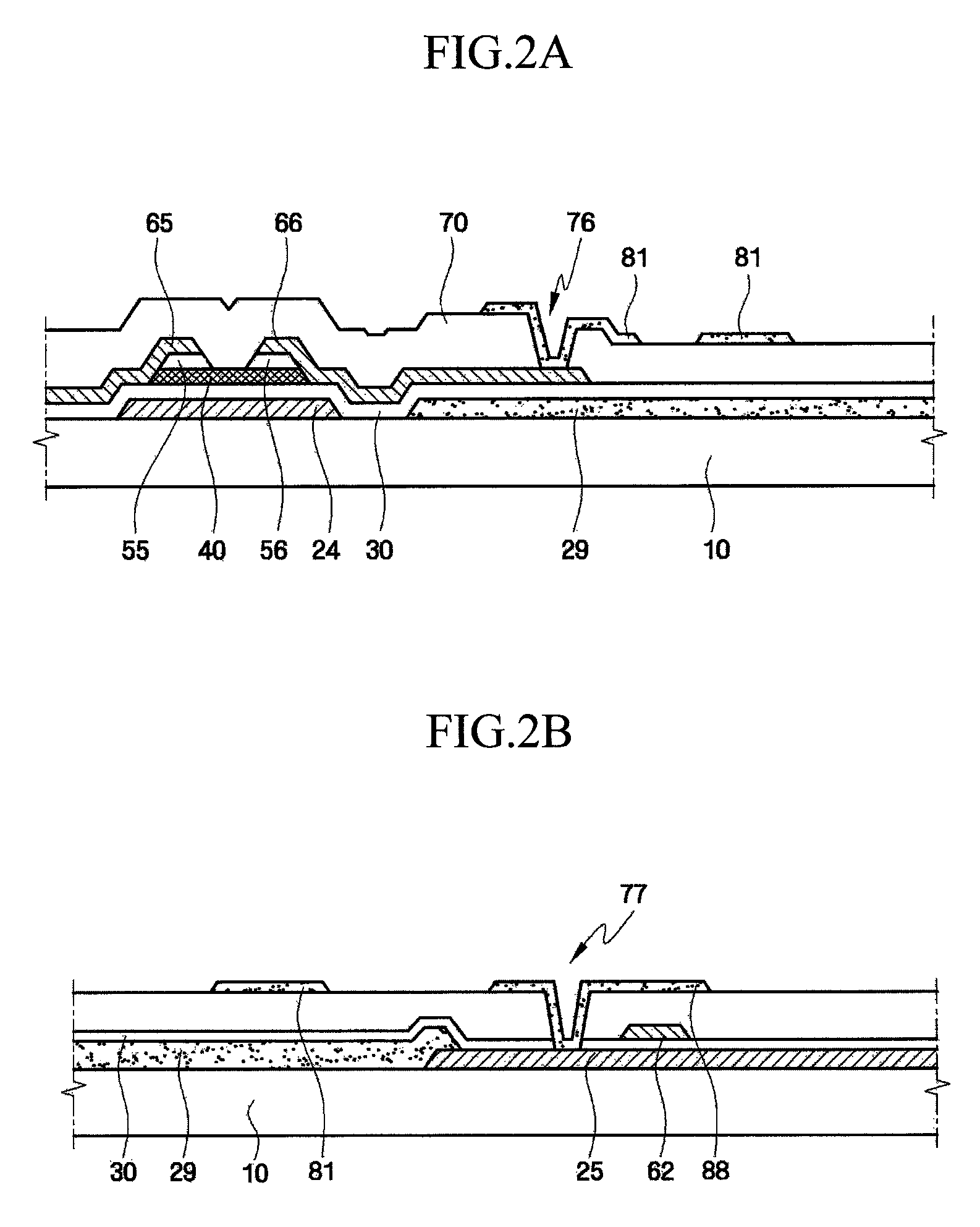
[0024]FIGS. 1 to 4 illustrate a liquid crystal display (LCD) according to an exemplary embodiment of the present invention. FIG. 1 is a layout view of a thin-film tra...


PUM

PropertyMeasurementUnit
lengthaaaaaaaaaa
thicknessaaaaaaaaaa
relative dielectric constantaaaaaaaaaa

Abstract

A liquid crystal display (LCD) has pixels with large effective aperture ratios. The LCD includes: a first insulating film formed over the gate line and the common electrode; a data line formed over the first insulating film, the data line crossing over the gate line, the data line being bent in a zigzag manner; a second insulating film formed over the data line; a pixel electrode formed over the second insulating film and comprising a plurality of subpixel electrodes substantially parallel to the data line, the pixel electrode comprising a connecting electrode interconnecting the subpixel electrodes; a shielding electrode formed over the second insulating film to overlie the data line; and a liquid crystal layer.

Description

[0001]This application claims priority from South Korean Patent Application No. 10-2008-0014463 filed on Feb. 18, 2008 in the Korean Intellectual Property Office, the disclosure of which is incorporated herein by reference in its entirety.BACKGROUND OF THE INVENTION[0002]1. Field of the Invention[0003]The present invention relates to a liquid crystal display (LCD), and more particularly, to an LCD whose pixels have increased effective aperture ratios and thus improved light transmission.[0004]2. Description of the Related Art[0005]Liquid crystal displays (LCDs) are among the most widely used types of flat panel displays (FPDs). An LCD includes a liquid crystal layer between two substrates with electrodes. The LCD rearranges the molecules of the liquid crystal layer by applying voltages to the electrodes to control the amount of light transmitted through the liquid crystal layer to display a desired image.[0006]LCDs can be easily made thin and can consume relatively little power and ...

Claims


Application Information

Patent Timeline
Patent Type & Authority Patents(United States)
IPC IPC(8): G02F1/1343
CPCG02F1/134363G02F1/13439G02F1/1343
Inventor KIM, DONG-GYU
Owner SAMSUNG DISPLAY CO LTD
Learn More