Bragg reflector grating

a reflector and grating technology, applied in the field of bragg reflector gratings, can solve the problems of general difficulty in distinguishing the effect of one section from the other, and achieve the effects of increasing the pitch range, and increasing the pitch rang

Active Publication Date: 2012-04-17
LUMENTUM TECH UK LTD
View PDF5 Cites 0 Cited by
  • Summary
  • Abstract
  • Description
  • Claims
  • Application Information

AI Technical Summary

Benefits of technology

[0020]The skilled person is likely to regard such an increase in pitch ranges as being disadvantageous, because increasing the pitch range produces a wider reflection spectrum (i.e. a greater range of wavelengths at which the chirped grating section reflects). However, there are at least some circumstances in which it is in fact advantageous. For example, as indicated above in relation to the known arrangements shown in FIGS. 1 and 2, one DBR grating reflector of a tuneable laser may be designed to produce a “comb” of reflection peaks that are separated in wavelength, and an opposite DBR grating reflector of the laser may comprise chirped grating sections that are tuned to produce a reinforced reflection peak with which one of the reflection peaks of the comb coincides, in order to cause the laser to lase at that wavelength. For such arrangements, a broader reinforced peak (i.e. containing a broader range of wavelengths) can allow a greater tuning range for the reflection peak from the “comb”, within the reinforced peak. Consequently, the provision of chirped grating sections with broader grating pitch ranges can provide improved wavelength tuning control. Such improved wavelength tuning control may make the laser less sensitive to any inaccuracies in the tracking during tuning of the reflective peaks of the front and rear gratings corresponding to the lasing peak (e.g. such as due to non-uniformities in tuning performance). It can also permit greater manufacturing tolerances, because a greater degree of variability in construction can be accommodated. An increase in permitted manufacturing tolerances can increase manufacturing yield, because fewer devices need to be rejected.
[0021]The skilled person will understand that, alternatively, the range of wavelengths provided in the reflection peak of each chirped grating section of a DBR grating could be increased by making each section shorter in length whilst maintaining the same pitch range, because this would broaden the sinc2 part of the reflection spectrum. However, shortening the whole DBR grating (whilst maintaining the same grating pitch range) would produce a DBR grating with a weaker reflective strength. This would have the undesirable consequence of disturbing the balance of the reflection strengths between the front and back reflection gratings of a laser. In contrast, by means of the present invention it is possible to maintain the same average reflective strength of a chirped DBR grating reflector as a whole. Thus, the invention enables increased freedom in DBR grating design. Additionally, it allows a change in the optical properties of a DBR laser without changing the layout of the laser (i.e. its size and shape).
[0023]In some preferred embodiments of the invention, only a portion (i.e. not all) of the chirped grating sections of the DBR grating have one or more grating pitches in common with another grating section of the DBR grating. For example, for some applications it can be advantageous for one or more chirped grating sections having grating pitch ranges approximately in the middle of the entire range of grating pitches for the entire DBR grating, to have partially overlapping grating pitch ranges. This can be advantageous because the gain spectrum of the gain section of a tuneable laser is typically peaked with a maximum towards the middle of the tuning range, which can lead to a non-uniformity in the laser's side-mode suppression ratio (SMSR). By producing a DBR grating in which sections corresponding approximately with the middle of the pitch range include pitch range overlaps (while those at the ends of the range do not, or at least have smaller overlaps), the reinforced reflection peaks will generally be stronger (of greater power) at the ends of the wavelength range than in the middle. This can serve to improve the uniformity of the SMSR across the tuning range, and thus can increase performance and / or manufacturing yield. More generally, the degree of overlapping of the pitch ranges of the chirped grating sections, and the positioning of such overlapping within the wavelength tuning range, can be tailored to produce a desired effect on the reflection spectrum of the DBR grating, and thus, for example, on the emission spectrum of a tuneable laser incorporating the DBR grating.
[0028]It will be understood, therefore, that the invention enables there to be a large degree of flexibility in the grating pitches that the DBR grating can provide. This flexibility is achieved by means of the discontinuities in the grating pitch range of the DBR. Such discontinuities preferably comprise partial overlaps in the grating pitch ranges of the chirped grating sections, but they may additionally or alternatively comprise absences in the grating pitch range of the DBR. The flexibility enables Bragg reflector gratings to be designed to meet any of a variety of different requirements. In particular, it enables the provision of a variety of tuneable lasers, meeting any of a variety of requirements.

Problems solved by technology

(It should be noted that it is generally difficult to distinguish the effect of one section from the others until they are tuned relative to one another.)

Method used


Image

  • Bragg reflector grating
  • Bragg reflector grating
  • Bragg reflector grating

Examples


Embodiment Construction

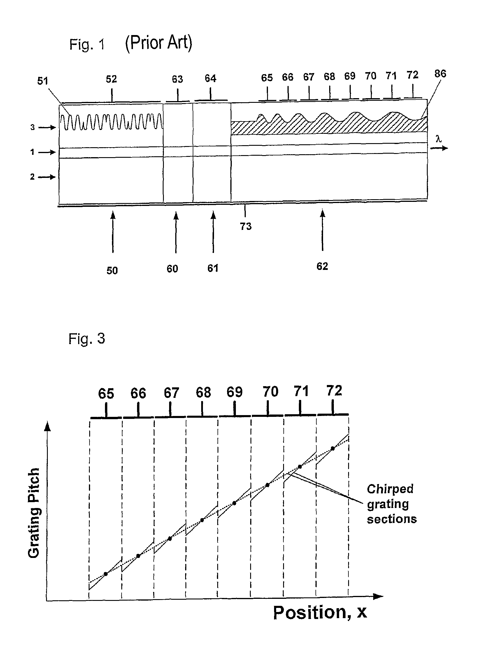
[0040]FIGS. 1 and 2 are described above.

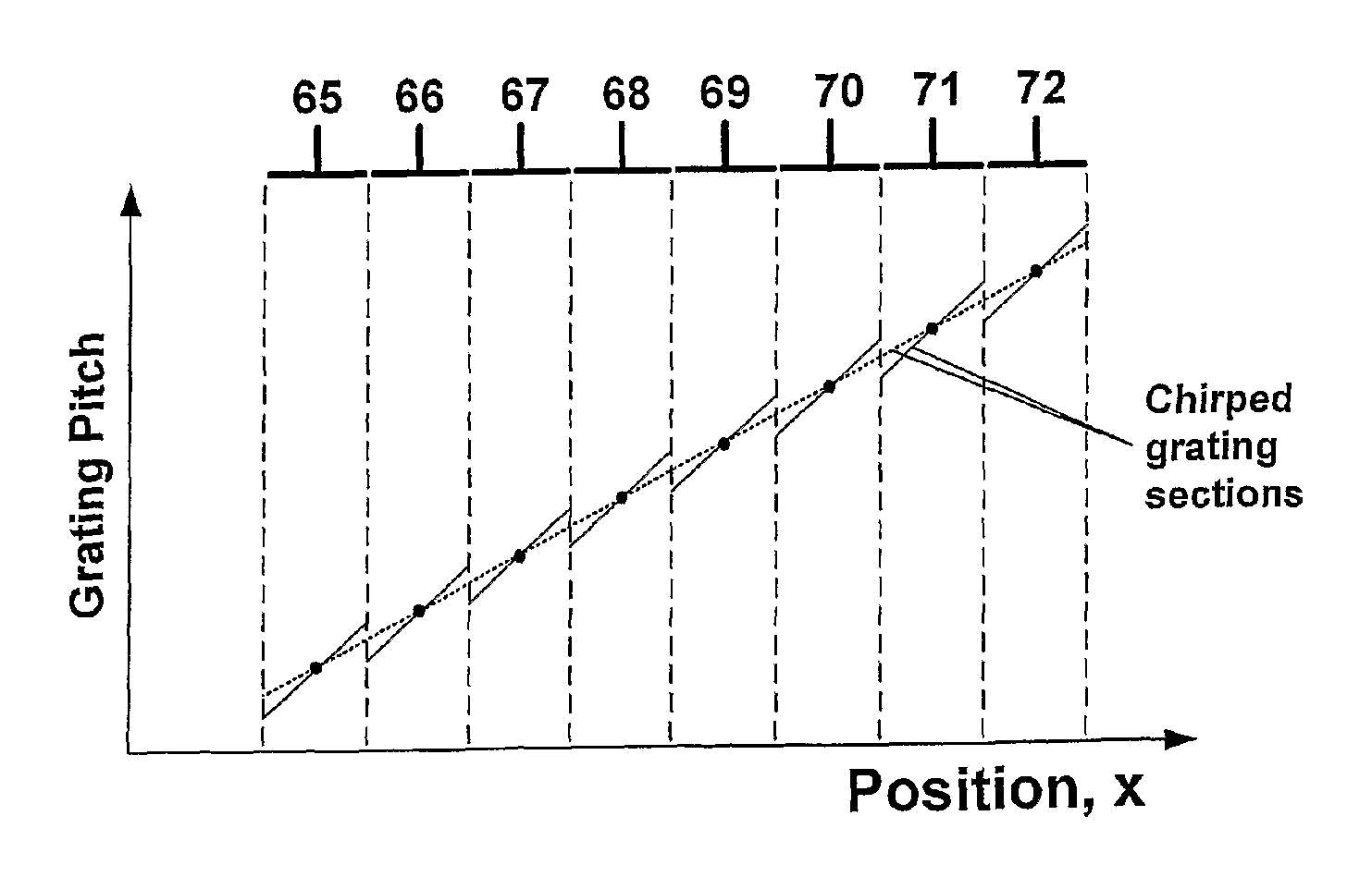
[0041]FIG. 3 is a schematic diagram, similar to the type of diagram included in FIG. 2, showing the variation in grating pitch of an embodiment of a distributed Bragg reflector grating according to the invention. In particular, the diagram shows the variation in grating pitch as a function of position along the grating. The entire grating includes eight chirped grating sections, each of which has a respective electrical contact (electrode) associated with it, indicated by the reference numerals 65-72. The variation in grating pitch for a known monotonically chirped grating (also comprising eight chirped grating sections of corresponding length) is indicated, for comparison, by the dotted line. Each of the chirped grating sections of the grating according to the invention is shown to have a greater range of grating pitches than a corresponding chirped grating section of a conventional grating with the same profile of median grating pitches. Con...


PUM


Abstract

A Bragg reflector grating comprises a plurality of chirped grating sections (65-72), in which at least a first chirped grating section and a second chirped grating section have differing ranges of grating pitches. The combined range of grating pitches provided by the first and second chirped grating sections includes at least one discontinuity, such that the first and second chirped grating sections have one or more grating pitches in common and / or there are one or more ranges of grating pitches within the combined range of grating pitches that are absent.

Description

RELATED APPLICATIONS[0001]This application is a 35 U.S.C. 371 national stage filing of International Application No. PCT / GB2006 / 004578, filed 8 Dec. 2006, which claims priority to Great Britain Patent Application No. 0524994.1 filed on 8 Dec. 2005 in Great Britain. The contents of the aforementioned applications are hereby incorporated by reference.FIELD OF THE INVENTION[0002]The present invention relates to Bragg reflector gratings, and especially relates to distributed Bragg reflector gratings. The invention has particular utility in the field of integrated optical devices, particularly laser devices, and especially tuneable laser devices.BACKGROUND ART[0003]Distributed Bragg reflector gratings (DBR gratings) are well known in the art, and are formed from patterned refractive index changes along an optical path. In the case of a semiconductor waveguide the grating is commonly formed by etching a lithographic pattern into the structure part way through an epitaxial growth process, ...

Claims


Application Information

Patent Timeline
Patent Type & Authority Patents(United States)
IPC IPC(8): G02B6/34G02B5/18H01S3/08
CPCH01S5/06256G02B6/02085G02B2006/12107H01S5/1212H01S5/1215G02B6/124H01S3/1055
Inventor REID, DOUGLAS CHARLES JOHNWARD, ANDREW JOHN
Owner LUMENTUM TECH UK LTD
Why Eureka
Try Eureka