Device and method for automatic detection of incorrect measurements by means of quality factors

a technology of quality factors and automatic detection, applied in the direction of speed/acceleration/shock measurement devices, color television, testing/calibration of speed/acceleration/shock, etc., can solve the problem of uncorrect detection of variable g to be measured, inability to make measurements without errors, measurement can be disrupted, etc. problem, to achieve the effect of reliable identification of an incorrect measurement, optimised measurement accuracy, and reduced throughput of the coordinate measuring machin

Active Publication Date: 2012-04-10
VISTEC SEMICON SYST JENA
View PDF14 Cites 0 Cited by
  • Summary
  • Abstract
  • Description
  • Claims
  • Application Information

AI Technical Summary

Benefits of technology

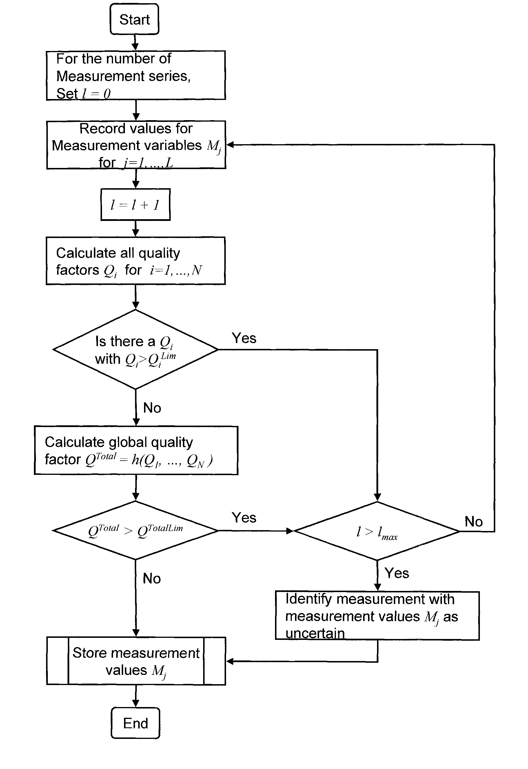
[0018]It is therefore an object of the present invention to provide a device which reliably identifies an incorrect measurement without the throughput of the coordinate measuring machine being unacceptably reduced thereby, and such that the short-term and long-term reproducibility and the accuracy of the measurement are optimised.
[0020]It is a further object of the invention to provide a method with which an incorrect measurement is reliably identified without the throughput of the coordinate measuring machine being unacceptably reduced thereby, and such that the short-term and long-term reproducibility and accuracy of the measurement are optimised.
[0032]In a preferred embodiment of the present invention, the functions ƒi are determined so that the respective associated quality factor Qi correlates to the variable G. In this case, exceeding of the quality limit QiLim by passing or undershooting (depending on the type of measurement variable Mj) also represents an incorrect measurement for this Qi. The danger that a good measurement will be rejected is therefore significantly reduced.

Problems solved by technology

It is fundamentally impossible to make measurements without errors.
Due to various causes, the variable G to be measured is not correctly detected.
A position measurement can be disrupted, for example, by the sudden opening of a door or by floor vibration and thereby lead to incorrect measurements.
However, the coordinate measuring machine is not suitable for calculating an analysis of specified measurement variables Mj with regard to a possible incorrect measurement.
These measuring devices are not provided for determining the position coordinates of the structural elements.
A further disadvantage of this method lies in the large number of parameters that must be taken into account in the form of correction values.

Method used


Image

  • Device and method for automatic detection of incorrect measurements by means of quality factors
  • Device and method for automatic detection of incorrect measurements by means of quality factors
  • Device and method for automatic detection of incorrect measurements by means of quality factors

Examples


Embodiment Construction

[0058]FIG. 1 shows a schematic representation of an embodiment of a coordinate measuring machine 1 as previously described in detail in the prior art and therefore also known in detail from the prior art. The coordinate measuring machine 1 comprises a measuring table 20 movable in the X-coordinate direction and in the Y-coordinate direction. The measuring table 20 carries a substrate 2 which may be a mask 2 made, for example, from quartz glass. The mask 2 is used for the production of semiconductors, for example, wafers. A plurality of structures 3 is placed on the surface of the substrate 2. The measuring table 20 itself is supported on guide bearings or air bearings 21 which in turn can be supported on a granite block 25. Other types of block are also conceivable. It is herein only required that the block defines a plane 25a in which the measuring table 20 can be displaced. For the illumination of the substrate 2, at least one reflected light illumination apparatus 14 and / or one t...


PUM


Abstract

What is disclosed is a device (1) for automatic detection of a possible incorrect measurement, wherein the device (1) comprises at least one reflected light illumination apparatus (14) and / or a transmitted light illumination apparatus (6) and at least one imaging optical system (9) and one detector (11) of a camera (10) for imaging structures (3) on a substrate (2), wherein a first program portion (17) is linked to the detector (11) of the camera (10), said detector being provided for determining the position and / or dimension of the structure (3) on the substrate (2), wherein the device (1) determines and records a plurality of measurement variables Mj, jε{1, . . . , L}, from which at least one variable G can be determined, wherein a second program portion (18) is linked to the detector (11) of the camera (10), said program portion calculating an analysis of the measurement variables Mj with regard to a possible incorrect measurement. Also disclosed is a method for automatic detection of a possible incorrect measurement wherein an analysis of the measurement variables Mj with regard to a possible incorrect measurement is calculated with a second program portion (18) which is linked to the detector (11) of the camera (10).

Description

RELATED APPLICATIONS[0001]This application claims priority to German Patent Application No. 10 2007 009 446.0, filed on Feb. 23, 2007, and German Patent Application No. 10 2007 047 924.9, filed on Dec. 12, 2007, and claims the benefit under 35 USC 119(e) of U.S. Provisional Application No. 60 / 891,333 filed on Feb. 23, 2007, all of which are incorporated herein by reference in their entirety.BACKGROUND OF THE INVENTION[0002]The invention relates to a device for automatic detection of a possible incorrect measurement. In particular, the invention relates to the automatic detection of a possible incorrect measurement in a coordinate measuring machine, wherein the device comprises at least one reflected light illumination apparatus and / or a transmitted light illumination apparatus and at least one imaging optical system and one detector of a camera for imaging structures on a mask (substrate), wherein a first program portion is linked to the detector of the camera, said detector being p...

Claims


Application Information

Patent Timeline
Patent Type & Authority Patents(United States)
IPC IPC(8): H04N7/18G06K9/00G01B11/14
CPCG01B21/045G03F1/84G01N2021/95676H01J2237/24592
Inventor BOESSER, HANS-ARTURHEIDEN, MICHAELADAM, KLAUS-DIETER
Owner VISTEC SEMICON SYST JENA
Why Eureka
Try Eureka