
Nitride semiconductor device

a semiconductor and nitride technology, applied in the direction of semiconductor devices, basic electric elements, electrical appliances, etc., can solve the problems of difficult light evenly emitted, and achieve the effect of enhancing luminescence characteristics and low resistan

Inactive Publication Date: 2012-04-10
ROHM CO LTD
View PDF15 Cites 2 Cited by
  • Summary
  • Abstract
  • Description
  • Claims
  • Application Information

AI Technical Summary

Benefits of technology

[0022]Further, there has also been proposed to increase a thicknesses of the respective layers of the n-type semiconductor layer between the n-electrode 614 and the MQW active layer 605, so as to make a distance from the n-electrode 614 to the MQW active layer 605 long enough so that the electric current can flow up to the MQW active layer 605 while diffusing uniformly. However, this causes a problem of increasing the time for a crystal growth and thereby increasing the manufacture cost. Moreover, since the distance to the substrate from a supporting substrate that supports the nitride semiconductor layer increases, when the nitride semiconductor layer is separated from the substrate, a stress applied on the nitride semiconductor layer increases and causes damages in the nitride semiconductor layer.
[0024]The present invention has been made in view of the above-described problems, and has an object of providing a nitride semiconductor device, which has enhanced luminescence characteristics and a thin layer thickness of an n-type semiconductor layer between an n-electrode and an active layer.
[0026]According to the first aspect of the invention, the generating layer including at least any one of AlxGa1-xN (0<x<1) and InxGa1-xN (0<x<1) is provided on the n-type GaN contact layer including the n-type impurity-doped GaN having an electron concentration ranging from 5×1016 cm−3 to 5×1018 cm−3. Thereby, when an electric current is caused to flow between the n-electrode and the p-electrode, the electron accumulation layer can be generated at the boundary surface between the n-type GaN contact layer and the generating layer. The electron accumulation layer accumulates electrons two-dimensionally near the boundary surface between the n-type GaN contact layer and the generating layer and allows the electric current to easily flow because of low resistance.
[0027]Accordingly, when the electric current flows between the n-electrode and the p-electrode in the nitride semiconductor device, the electric current which has flowed from the n-electrode diffuses approximately in the horizontal direction with respect to the crystal growth direction in the electron accumulation layer to promptly diffuse in the entire electron accumulation layer. The electric current diffused in the electron accumulation layer via the electron accumulation layer flows uniformly to the active layer, thereby allowing the active layer to emit light evenly. Thus, since the electric current can be diffused evenly in the electron accumulation layer, the nitride semiconductor device, which has enhanced luminescence and a thin layer thickness of the n-type semiconductor layer between the n-electrode and the active layer, can be obtained.
[0031]According to this aspect, the generating layer has the superlattice structure and the thickness per layer is less than or equal to 30 nm. Accordingly, the electrons are further accumulated two-dimensionally near the boundary surface between the n-type GaN contact layer and the generating layer, and the electron accumulation layer having low resistance can be generated. Accordingly, the nitride semiconductor device, which has enhanced luminescence characteristics and a thin layer thickness of the n-type semiconductor layer between the n-electrode and the active layer, can be obtained.

Problems solved by technology

Moreover, the nitride semiconductor device has a problem that the MQW active layer 605 has difficulty in emitting light evenly, since the electric current diffused uniformly hardly flows up to the MQW active layer 605.

Method used


Image

  • Nitride semiconductor device
  • Nitride semiconductor device
  • Nitride semiconductor device

Examples


first embodiment

(Configuration of Nitride Semiconductor Device of the Present Invention)

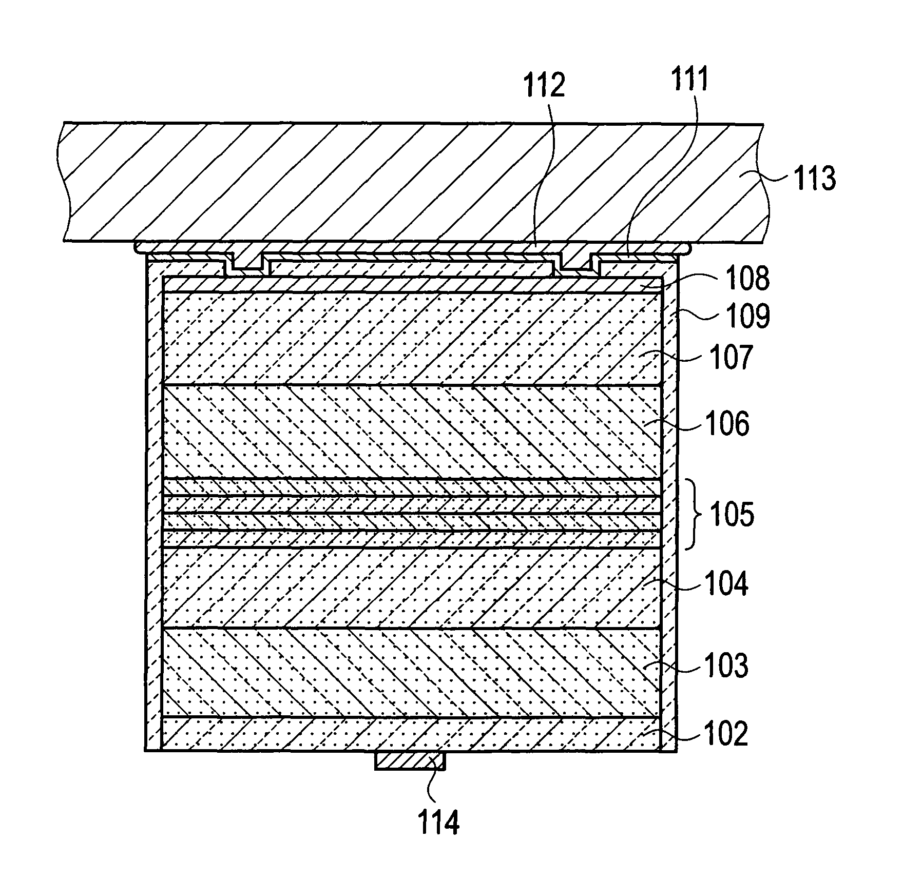
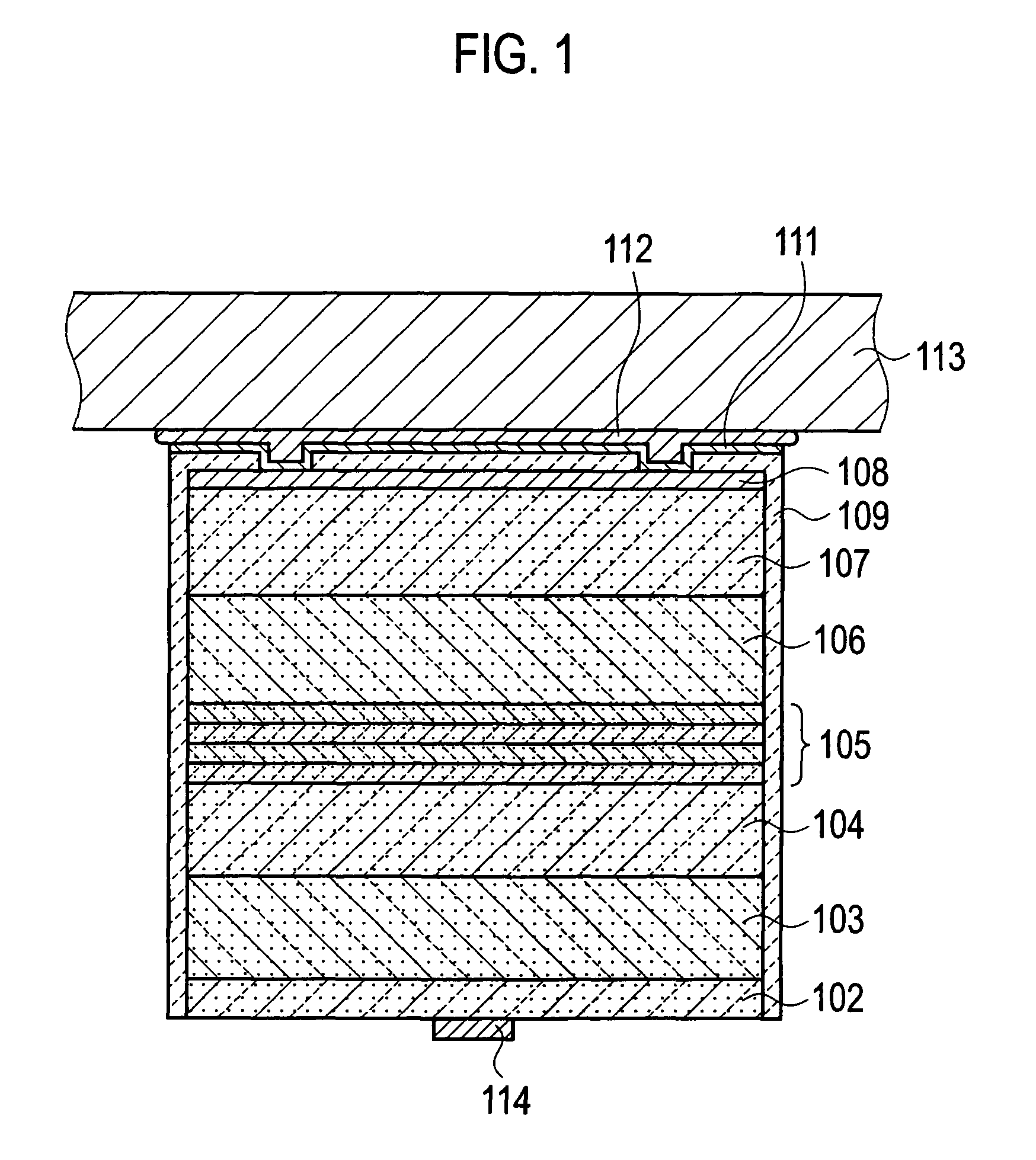
[0047]A nitride semiconductor device according to a first embodiment of the present invention will be described with reference to FIG. 1. FIG. 1 shows the sectional structure of the nitride semiconductor device according to the first embodiment of the present invention. As an example of the nitride semiconductor device according to this embodiment, a description will be given of a blue LED used as a light source and a blue LED and green LED used as light sources for white lighting.

[0048]As shown in FIG. 1, the nitride semiconductor device according to this embodiment includes a nitride semiconductor layer in which an n-type semiconductor layer, an MQW active layer 105, and a p-type semiconductor layer are laminated.

[0049]In the nitride semiconductor device according to the first embodiment, the n-type semiconductor layer is a nitride semiconductor layer laminated between an n-electrode 114 and the MQW active la...

second embodiment

(Nitride Semiconductor Device of the Present Invention)

[0105]A nitride semiconductor device according to a second embodiment of the present invention will further be described below with reference to FIG. 7.

[0106]Note that the differences from the first embodiment described above will mainly be described below.

[0107]In the first embodiment, the n-type AlGaN layer 103, which is formed of Si-doped Al0.08GaN and generates the electron accumulation layer, is formed as the generating layer on the n-type GaN contact layer 102.

[0108]In contrast, in the second embodiment, an n-type InGaN layer 203 formed of InxGa1-xN (0202.

[0109]For example, the n-type InGaN layer 203 is formed of Si-doped In0.05GaN.

[0110]Note that the composition of the n-type InGaN layer 203 is not limited to In0.05GaN, as long as InxGa1-xN (0203 hereinafter).

[0111]The n-type semiconductor layer includes the n-type GaN contact layer 202 formed of Si-doped GaN having an electron concentration ranging from 5×1016 cm−3 to 5...

third embodiment

(Nitride Semiconductor Device of the Present Invention)

[0113]A nitride semiconductor device according to a third embodiment of the present invention will further be described below with reference to FIG. 8.

[0114]Note that the differences from the first embodiment described above will mainly be described below.

[0115]In the first embodiment, on the n-type GaN contact layer 102, the n-type AlGaN layer 103 formed of Si-doped Al0.08GaN and generates the electron accumulation layer, is formed as the generating layer.

[0116]In contrast, in the third embodiment, on an n-type GaN contact layer 302, an InGaN / GaN superlattice layer 303 is formed as the generating layer. The InGaN / GaN superlattice layer 303 has a superlattice structure in which an InxGa1-xN (0yGa1-yN (0≦yxGa1-xN layer and the InyGa1-yN layer has a thickness of less than or equal to 30 nm.

[0117]For example, the InGaN / GaN superlattice layer 303 is formed to have a superlattice structure in which an InGaN layer formed of Si-doped ...


PUM


Abstract

A nitride semiconductor device according to the present invention sequentially includes at least an n-electrode, an n-type semiconductor layer, an active layer, and a p-type semiconductor layer. The n-type semiconductor layer includes: an n-type GaN contact layer including n-type impurity-doped GaN having an electron concentration ranging from 5×1016 cm−3 to 5×1018 cm−3; the n-electrode provided on one of a main surface of the n-type GaN contact layer; and a generating layer provided on other main surface of the n-type GaN contact layer, including at least any one of AlxGa1-xN (0<x<1) and InxGa1-xN (0<x<1), and generates an electron accumulation layer for accumulating layer electrons at a boundary surface with the n-type GaN contact layer.

Description

[0001]This application is a 371 of PCT / JP2007 / 052264, filed Feb. 8, 2007TECHNICAL FIELD[0002]The present invention relates to a nitride semiconductor device, which includes at least an n-electrode, an n-type semiconductor layer, an active layer, and a p-type semiconductor layer, sequentially.BACKGROUND ART[0003]Heretofore, nitride semiconductor devices have been used in blue LEDs (light emitting diodes) serving as light sources for lightings, backlights, and the like, and in green LEDs serving as light sources for white lightings. Further, in a white lighting, white color is formed by using a red LED, a blue LED, and a green LED.[0004]As shown in FIG. 11, in the nitride semiconductor device, a nitride semiconductor layer formed of an n-type semiconductor layer, an MQW active layer 505, and a p-type semiconductor layer are laminated on a substrate 500. It is preferable that the substrate 500 has conductive properties so that the substrate 500 can form a path for electric current to f...

Claims


Application Information

Patent Timeline
Patent Type & Authority Patents(United States)
IPC IPC(8): H01L33/00H01L33/06H01L33/10H01L33/32
CPCH01L33/04H01L33/32H01L33/0079H01L33/0093
Inventor NAKAHARA, KEN
Owner ROHM CO LTD
Learn More