Exercise tool

a technology of exercise tools and tools, applied in the direction of sports equipment, muscle exercise devices, gymnastic exercise, etc., can solve the problems of poor degree of freedom in the direction of movement, limited rotation direction of each hand, and load applied from the coil spring, etc., to achieve convenient replacement, sufficient degree of freedom, and facilitate the effect of changing the magnitude of the load applied

Inactive Publication Date: 2012-04-10
SANRIKI INDS +1
View PDF6 Cites 3 Cited by
  • Summary
  • Abstract
  • Description
  • Claims
  • Application Information

AI Technical Summary

Benefits of technology

[0014]In view of the foregoing, an object of the present invention is to provide an exercise tool which guarantees a sufficient degree of freedom in the direction of movement of the wrists and facilitates changing the magnitude of the load applied during the wrist exercise, thereby enabling more effective strengthening of the deep muscles.
[0018]With the exercise tool of the present invention, the first rod body and the second rod body are configured to be rotatable in opposite directions from each other and movable away from each other against the biasing force applied by the elastic member. This ensures a sufficient degree of freedom in the direction of movement of the wrists. Furthermore, the elastic member has one end and the other end removably latched by the first and second elastic-member latch bodies, respectively. This allows the elastic member to be readily replaced with another one having a different elastic force, thereby facilitating changing the magnitude of the load applied during the wrist exercise.
[0019]According to the exercise tool of the present invention, a sufficient degree of freedom in the direction of movement of the wrists is guaranteed and the magnitude of the load applied to the wrists during the exercise can be changed with ease, whereby the deep muscles can be strengthened more effectively.

Problems solved by technology

With this wrist twisting exercise tool, however, the load is applied from the coil spring only in the case where the outer tube is rotated in the direction opposing the wound direction of the coil spring.
This means that the direction in rotating each of the left and right hands is limited to one direction.
The user cannot alternately rotate the left and right hands frontward and backward while holding the outer tubes, resulting in a poor degree of freedom in the direction of movement.
This restricts the type of exercise only to the wrist rotation exercise, again resulting in a poor degree of freedom in the direction of movement.
Still further, the coil springs are attached inside the outer tubes, hindering replacement thereof.
Therefore, the magnitude of the load cannot be changed easily.
If a sufficient degree of freedom in the direction of movement of the wrists cannot be maintained or if the magnitude of the load in the wrist exercise cannot be changed easily, as in the above-described case, the deep muscles cannot be strengthened effectively.

Method used


Image

  • Exercise tool
  • Exercise tool
  • Exercise tool

Examples


first embodiment

(First Embodiment)

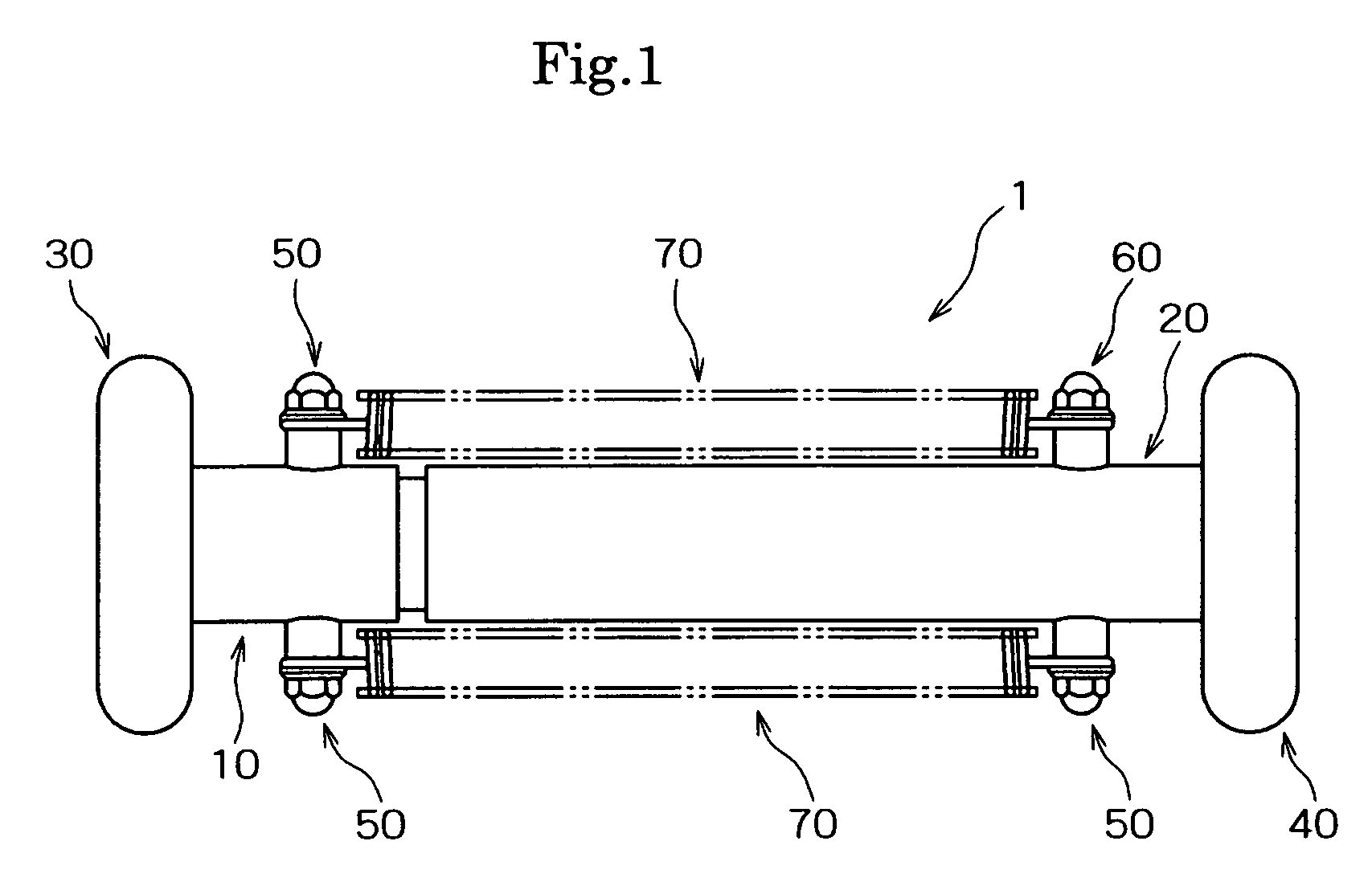
[0032]Hereinafter, preferred embodiments of the present invention will be described in detail. FIG. 1 is a front view of a first embodiment of the exercise tool according to the present invention, and FIG. 2 is a partially cut-away view of the exercise tool shown in FIG. 1.

[0033]Firstly, as shown in FIG. 1, an exercise tool 1 includes a first rod body 10, a second rod body 20, a first grip 30, a second grip 40, a first elastic-member latch body 50, a second elastic-member latch body 60, and coil springs 70.

[0034]According to the exercise tool 1 shown in FIG. 1, the details of which will be described later, the first rod body 10 and the second rod body 20 are configured to be rotatable in opposite directions from each other against the biasing force of the coil springs 70. Furthermore, the first rod body 10 and the second rod body 20 are configured to be movable away from each other against the biasing force of the coil springs 70 which are elastic members. Each coi...

second embodiment

(Second Embodiment)

[0076]With reference to FIGS. 5-6, a second embodiment of the present invention will be described in detail. FIG. 5 shows an exercise tool according to the second embodiment in which the configuration of the exercise tool 1 shown in FIGS. 1-2 has been modified. FIG. 6 illustrates how to use the exercise tool 1 shown in FIG. 5. It should be noted that in the figures, as will be described further below, the parts common to those shown in FIGS. 1-2 are denoted by the same reference characters, and description thereof will not be repeated as appropriate.

[0077]Firstly, the exercise tool 1 of the second embodiment differs from that of the first embodiment in that, as seen from FIG. 5, the tubular portion 11a with the larger outside diameter of the first rod body 10 in the exercise tool 1 is formed longer than that in the exercise tool 1 shown in FIGS. 1 and 2. Otherwise, the configuration of the exercise tool 1 of the second embodiment is approximately the same as that ...

third embodiment

(Third Embodiment)

[0081]Referring next to FIGS. 7-8, a third embodiment of the present invention will be described in detail. FIG. 7 shows an exercise tool according to the third embodiment in which the configuration of the exercise tool 1 shown in FIGS. 1-2 has been modified. FIG. 8 illustrates how to use the exercise tool 1 shown in FIG. 7.

[0082]Firstly, the exercise tool 1 of the third embodiment differs from that of the first embodiment in that, as seen from FIG. 7, the coil springs 70 have been replaced with elastic members 73 such as rubber, and that a coil spring 76 has been provided in the tube body 21 of the second rod body 20. Otherwise, the configuration of the exercise tool 1 of the third embodiment is approximately the same as that of the exercise tool 1 shown in FIGS. 1-2.

[0083]Each elastic member 73 shown in the figure has ring-shaped latch portions 74 and 75 at its respective ends. It is noted that the latch portions 74 and 75 may each be in a hook shape, not restric...


PUM


Abstract

An exercise tool is provided to ensure a good degree of freedom in the direction of movement of the wrists and allows the magnitude of the load applied to the wrists during the exercise to be changed easily so as to enable more effective strengthening of the deep muscles. The exercise tool has a first rod body 10 and a second rod body 20 which are rotatable in opposite directions and also movable away from each other against the biasing force of a coil spring 70. Ring-shaped latch portions 71 and 72 provided at respective ends of the coil spring 70 are removably latched by first and second elastic-member latch bodies 50 and 60, respectively, so that the coil spring 70 can readily be replaced with another coil spring 70 having a different elastic force, thereby facilitating changing the magnitude of the load applied during the wrist exercise.

Description

[0001]This application claims priority under 35 U.S.C. §119 from Japanese patent application Serial No. 2009-241983, filed Oct. 21, 2009, entitled “EXERCISE TOOL”, which is incorporated herein by reference in its entirety.TECHNICAL FIELD[0002]The present invention relates to an exercise tool and apparatus. More specifically it relates to an exercise tool suitable, e.g., for a wrist rotation exercise.BACKGROUND OF THE INVENTION[0003]A human body is covered with a large number of layers of muscles from the location near the center of the body close to the bones. The muscles in the relatively deep location are called “inner (or deep) muscles”, while the muscles near the body surface are called “outer (or superficial) muscles”.[0004]The deep muscles are responsible primarily for meticulously adjusting the postures and keeping the joints in the right positions. The superficial muscles are responsible for producing a large force.[0005]In order to maintain the activity of the deep and supe...

Claims


Application Information

Patent Timeline
Patent Type & Authority Patents(United States)
IPC IPC(8): A63B21/00
CPCA63B21/0004A63B21/00043A63B21/023A63B21/1496A63B23/14A63B21/00061A63B21/0428A63B2023/003A63B21/0455A63B21/0552A63B21/0557A63B21/0435A63B21/4049
Inventor WAKUDA, SHIGEKI
Owner SANRIKI INDS
Why Eureka
Try Eureka