Method for enhancing fracture propagation in subterranean formations

a technology of subterranean formations and fracture propagation, which is applied in the direction of earth drilling and mining, fluid removal, borehole/well accessories, etc., can solve the problems of difficult operation of conventional fracturing techniques, inability to achieve complex fracture networks away from the wellbore, and inability to achieve complex fracture networks. , to achieve the effect of enhancing the complexity of the far field of subterranean formations, increasing spacing distance, and increasing spacing distan

Active Publication Date: 2019-10-08
TEXAS TECH UNIV SYST
View PDF15 Cites 0 Cited by
  • Summary
  • Abstract
  • Description
  • Claims
  • Application Information

AI Technical Summary

Benefits of technology

[0011]The one or more complex fractures may connect to one or more pre-existing network of natural fractures to form the complex fracture network and the series of as fractures reduces a principal stress, a shear stress or both. The series of as fractures are generated as a function of a fluid flow and a stress interference and a minimum stress exists so that a net pressure can overcome a stress anisotropy to create a longer fracture. The series of as fractures can reduce a stress anisotropy between a first and second horizontal stresses and the series of as fractures changes the magnitude of horizontal stresses. The subterranean formation may be a shale or a tight sand reservoir.
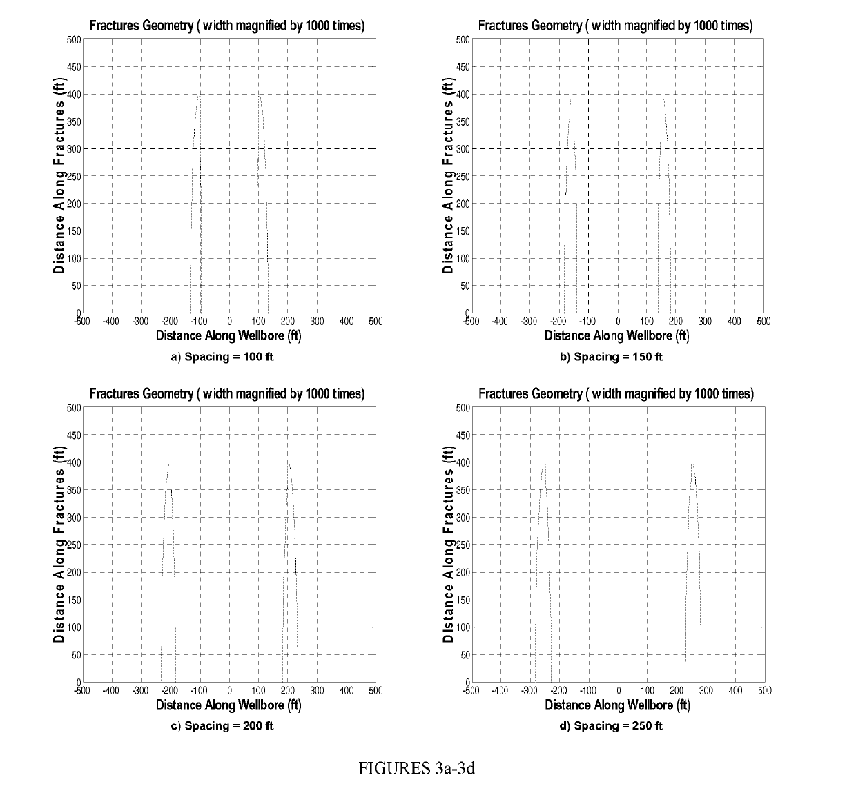
[0012]The present invention also provides a method of forming a series of non-uniformly spaced fractures penetrating an subterranean formation to form a complex network of hydraulically connected fractures by identifying a deviated wellbore in a subterranean formation; introducing a series of fractures in the deviated wellbore, wherein the series of fractures comprising at least a first fracture, a second fracture, a third fracture and a fourth fracture each separated by a non-uniformed and an increased spacing distance such that the spacing distance from each adjacent fracture in the series of fractures is at an increased distance; and forming one or more complex fractures extending from the series of fractures to form a complex fracture network.
[0014]In addition, the present invention also provides a method for enhancing far field complexity in subterranean formations during hydraulic fracturing treatments by means of optimizing the placement of fractures along the deviated wellbores. In this method two or more parallel laterals (deviated wells) may each be hydraulically fractured in a specific sequence forming a series of non-uniformly spaced fractures to alter the stress anisotropy in the formation. Each of the multiple deviated wellbores include a series of non-uniformly spaced fractures penetrating the subterranean formation to form a complex network of hydraulically connected fractures by identifying a deviated wellbore in a subterranean formation; introducing a series of fractures in the deviated wellbore, wherein the series of fractures comprising at least a first fracture, a second fracture, a third fracture and a fourth fracture each separated by a non-uniformed and an increased spacing distance such that the spacing distance from each adjacent fracture in the series of fractures is at an increased distance; and forming one or more complex fractures extending from the series of fractures to form a complex fracture network.
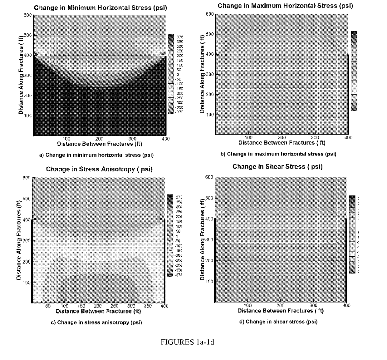
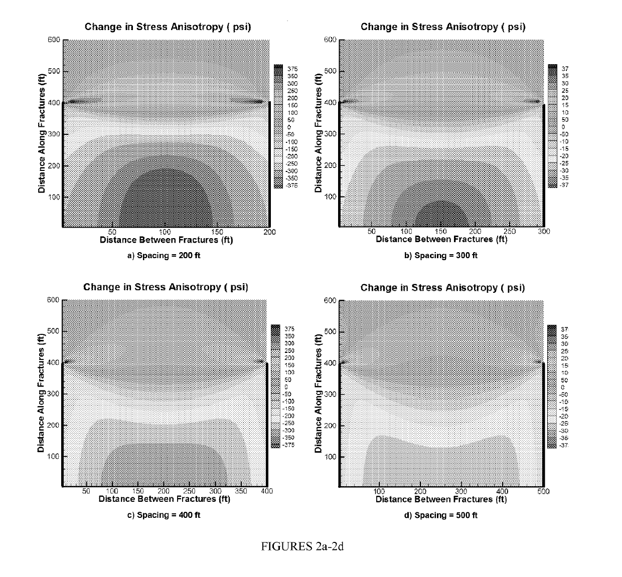
[0015]In another embodiment, the two or more parallel laterals (deviated wells) may each be hydraulically fractured in a specific sequence forming a series of non-uniformly spaced fractures to alter the stress anisotropy in the formation. If single cluster stages are to be designed, fractures in a specific sequence forming a series of non-uniformly spaced fractures such that after introducing the first and the second fractures in one of the wells, the third fracture may be created in the other well in a distance between the first two fractures. The third fracture extends to the area between the first two fractures and alters the stress field (changes the magnitude of horizontal stresses) in that region. Each of the multiple deviated wellbores include a series of non-uniformly spaced fractures penetrating the subterranean formation to form a complex network of hydraulically connected fractures by identifying a deviated wellbore in a subterranean formation; introducing a series of fractures in the deviated wellbore, wherein the series of fractures comprising at least a first fracture, a second fracture, a third fracture and a fourth fracture each separated by a non-uniformed and an increased spacing distance such that the spacing distance from each adjacent fracture in the series of fractures is at an increased distance; and forming one or more complex fractures extending from the series of fractures to form a complex fracture network. Since fractures tend to open in a direction perpendicular to the direction of minimum horizontal stress, the change in magnitude of SH minimum is larger than the change in the magnitude of SH maximum. Thus, after introducing the third fracture the different between two principal horizontal stresses (stress anisotropy) approaches zero. When there is no stress anisotropy in the subterranean formation, fractures may open in any direction and connect to the pre-existing network of natural fractures which eventually results in the creation of a complex network of fractures. A complex network of hydraulically connected fractures may improve the production of trapped hydrocarbons in tight subterranean formations such as shale and tight sand reservoirs.

Problems solved by technology

Creation of complex fracture networks away from the wellbore may not be achieved by conventional fracturing techniques.
Recently developed techniques are designed to overcome this problem however; those techniques are operationally difficult to perform.
Microcosmic mapping provides a good estimation of fracture geometry and stimulated reservoir volume (SRV); however, without geomechanical considerations, the predictions may not be completely accurate.

Method used


Image

  • Method for enhancing fracture propagation in subterranean formations
  • Method for enhancing fracture propagation in subterranean formations
  • Method for enhancing fracture propagation in subterranean formations

Examples


Embodiment Construction

[0031]While the making and using of various embodiments of the present invention are discussed in detail below, it should be appreciated that the present invention provides many applicable inventive concepts that can be embodied in a wide variety of specific contexts. The specific embodiments discussed herein are merely illustrative of specific ways to make and use the invention and do not delimit the scope of the invention.

[0032]To facilitate the understanding of this invention, a number of terms are defined below. Terms defined herein have meanings as commonly understood by a person of ordinary skill in the areas relevant to the present invention. Terms such as “a”, “an” and “the” are not intended to refer to only a singular entity, but include the general class of which a specific example may be used for illustration. The terminology herein is used to describe specific embodiments of the invention, but their usage does not delimit the invention, except as outlined in the claims.

[...


PUM


Abstract

The present invention provides a method of hydraulically fracturing a well penetrating an subterranean formation by optimizing the spacing of fractures along a wellbore to form a complex network of hydraulically connected fractures by identifying a deviated wellbore in a subterranean formation; introducing a series of fractures in the deviated wellbore, wherein the series of fractures comprising at least a first fracture, a second fracture, a third fracture and a fourth fracture each separated by a non-uniformed and an increased spacing distance such that the spacing distance from each adjacent fracture in the series of fractures is at an increased distance; and forming one or more complex fractures extending from the series of fractures to form a complex fracture network.

Description

CROSS-REFERENCE TO RELATED APPLICATIONS[0001]This application claims priority to, and is the National Stage of International Application No. PCT / US2013 / 061134 filed on Sep. 23, 2013 and claims the priority of U.S. Provisional Patent Application Ser. No. 61 / 709,792, filed on Oct. 4, 2012, the contents of which are incorporated by reference herein in their entirety.TECHNICAL FIELD OF THE INVENTION[0002]The present invention relates generally to compositions and methods for hydraulic fracturing of an earth formation and in particular, to compositions and methods for hydraulic fracturing by optimizing the placement of fractures along the deviated wellbores to enhance far field complexity and maximizing the stimulated reservoir volume.BACKGROUND ART[0003]Without limiting the scope of the invention, its background is described in connection with hydraulic fracturing to enhance production of trapped hydrocarbons. Conventional fracture designs focus on the creation of a fracture of desirabl...

Claims


Application Information

Patent Timeline
Patent Type & Authority Patents(United States)
IPC IPC(8): E21B43/26E21B43/30
CPCE21B43/305E21B43/26
Inventor SOLIMAN, MOHAMEDRAFIEE, MEHDIPIRAYESH, ELIAS
Owner TEXAS TECH UNIV SYST
Why Eureka
Try Eureka