
Photoelectric sensor for detecting presence/absence of object

Inactive Publication Date: 2007-07-24
HOSIDEN CORP
View PDF16 Cites 0 Cited by
  • Summary
  • Abstract
  • Description
  • Claims
  • Application Information

AI Technical Summary

Benefits of technology

[0008]According to an aspect of the present invention, there is provided a photoelectric sensor for detecting the presence/absence of an object in a detection area where a light-emitting area of a light-emitting device and a light-receiving area of a light-receiving device are overlapped with each other, the photoelectric sensor comprising: a power supply unit that outputs a driving current of the light-emitting device such that its current value is variable; and a control unit that controls the power supply unit in order to change in magnitude of the driving current o

Problems solved by technology

However, in the case where a plurality of light-emitting devices and light-receiving devices is used, there is a problem in that it is very difficult to realize miniaturization and cost-reduction of an apparatus.

Method used


Image

  • Photoelectric sensor for detecting presence/absence of object
  • Photoelectric sensor for detecting presence/absence of object
  • Photoelectric sensor for detecting presence/absence of object

Examples


Embodiment Construction

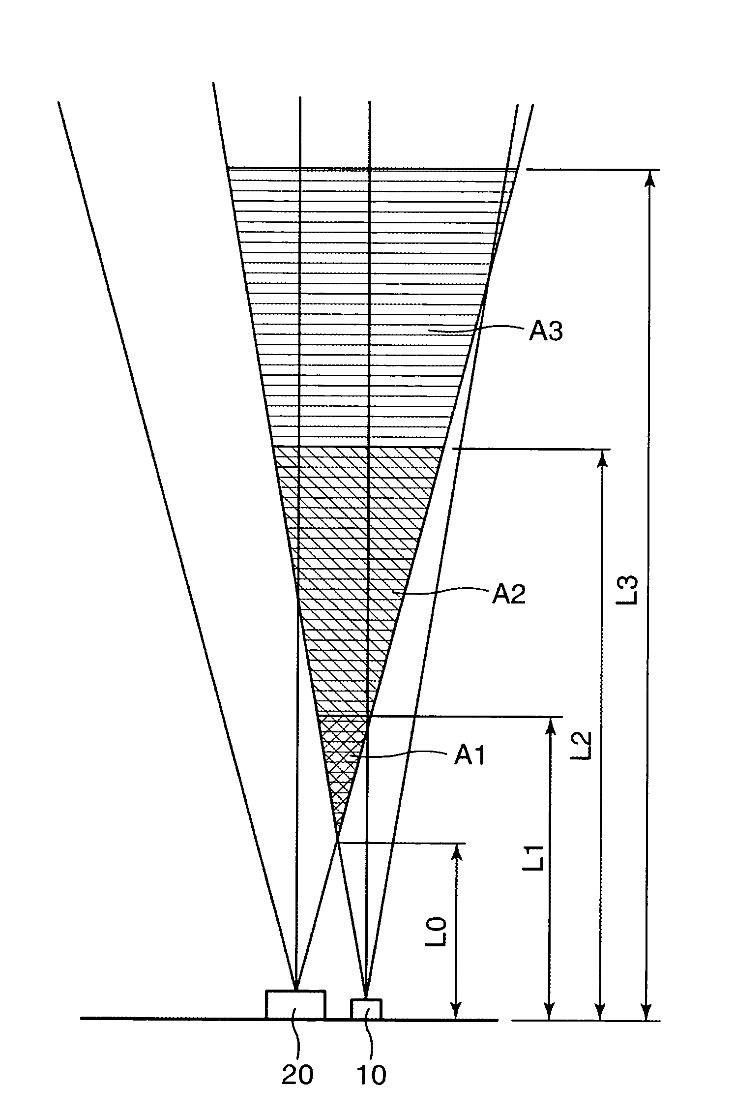
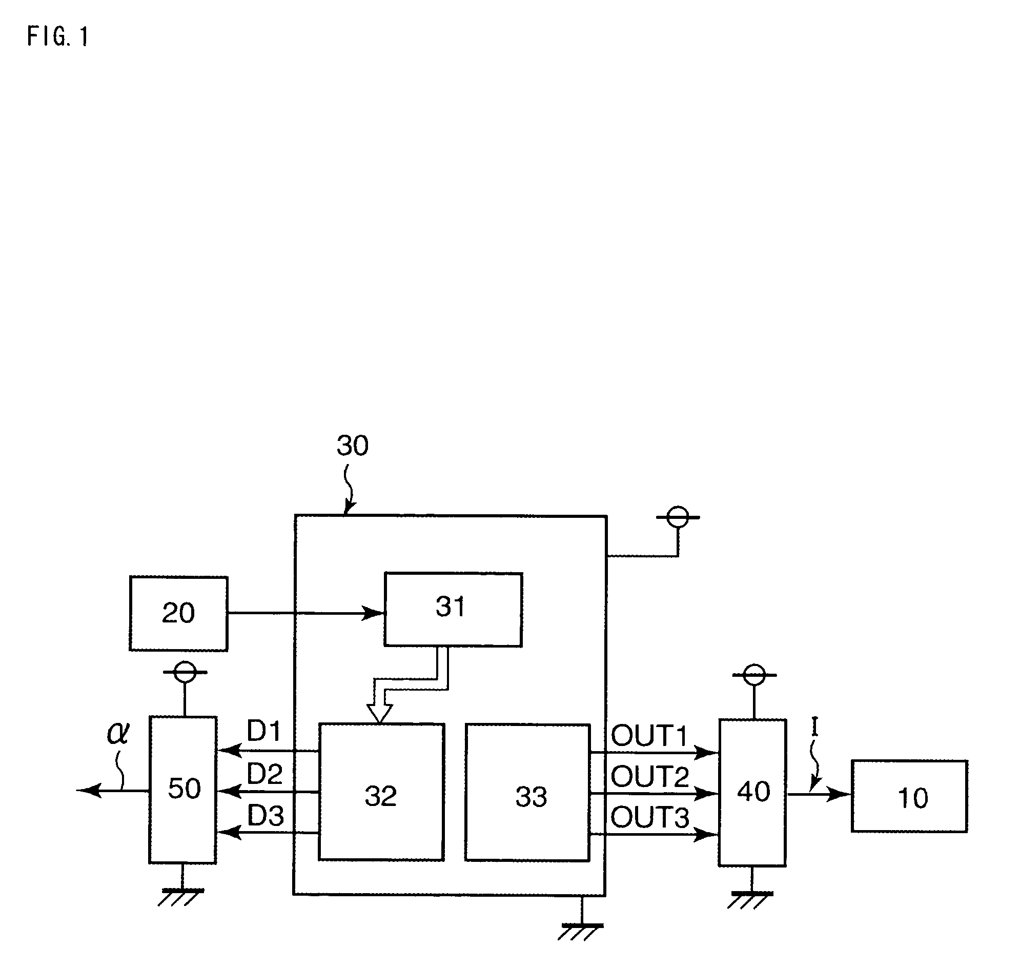
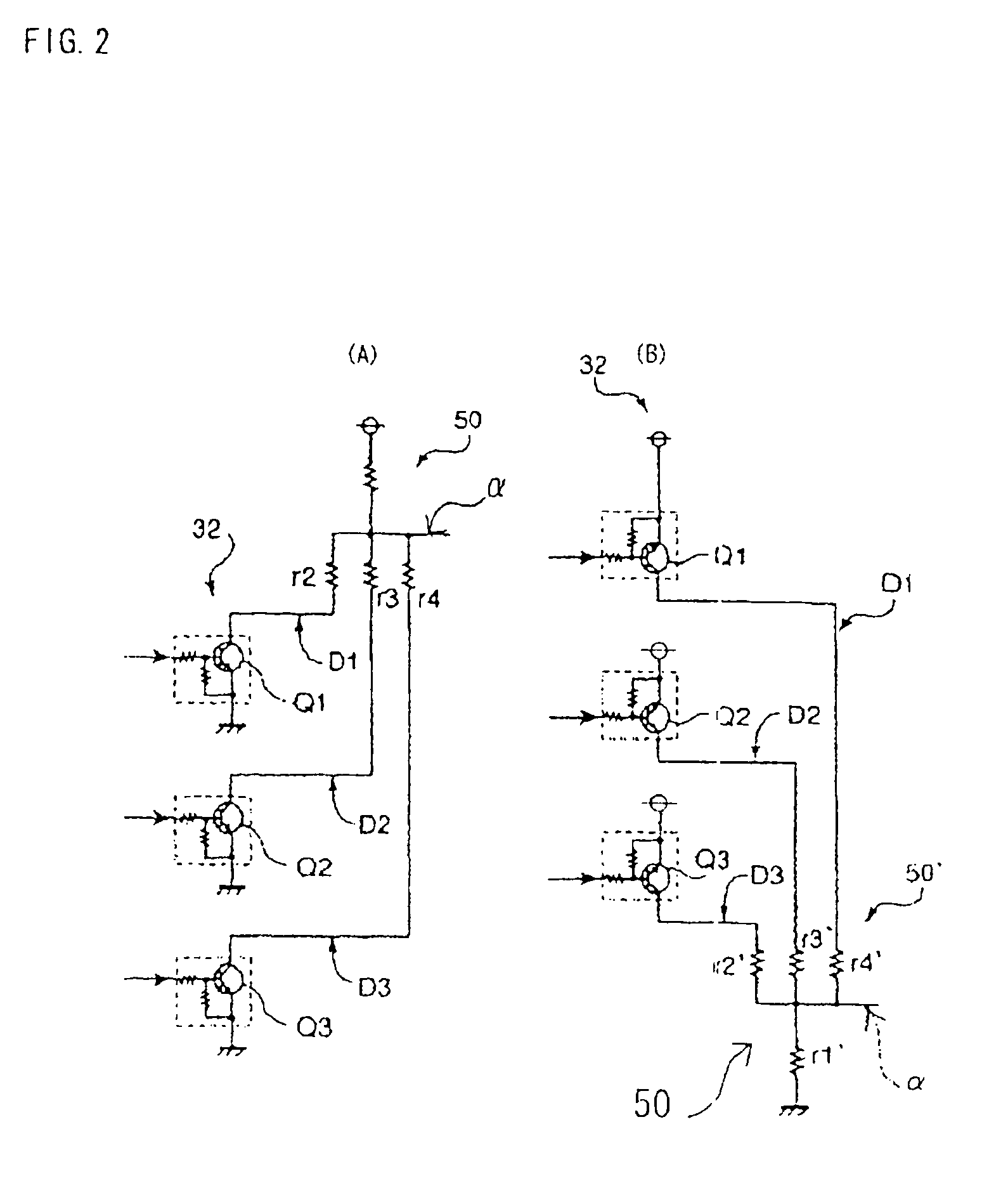
[0020]Hereinafter, description will be given of a first embodiment of the present invention with reference to FIGS. 1 to 4. FIG. 1 is a block diagram of a photoelectric sensor; FIGS. 2A and 2B are circuit diagrams showing output circuits in the photoelectric sensor, particularly, FIG. 2A shows an output circuit for N-channel and FIG. 2B shows an output circuit for P-channel; FIGS. 3A and 3B are timing charts in the photoelectric sensor showing operations of a power supply unit and the output circuit as shown in FIG. 2A, particularly, FIG. 3A shows the relationship between a control signal output from the control unit and a driving current of the light-emitting device: and FIG. 3B shows the relationship between a control signal output from a control unit and an output signal; and FIG. 4 is a view illustrating an object detection principle in the photoelectric sensor, which shows a detection area where a light-emitting area of a light-emitting device and a light-receiving area of a li...


PUM


Abstract

An object of the present invention is to enable the detection of the presence / absence of an object over a plurality of detection areas without using a plurality of light-receiving devices and light-emitting devices. A sensor detects the presence / absence of an object in a detection area where a light-emitting area of a light-emitting device and a light-receiving area of a light-receiving device are overlapped with each other, and includes: a power supply unit that outputs a driving current I of the light-emitting device such that its current value is variable; a control unit that has the function of controlling the power supply unit to change in magnitude of the driving current I of the light-emitting device, and determining the presence / absence of an object based on an output from the light-receiving device to output the result of determination as a detection signal; and an output signal 50 that converts the detection signal into an analog signal to output the converted signal as a signal α.

Description

BACKGROUND OF THE INVENTION[0001]1. Field of the Invention[0002]The present invention relates to a photoelectric sensor for detecting the presence / absence of an object using a light-emitting device and a light-receiving device.[0003]2. Description of the Related Art[0004]This kind of photoelectric sensor has a basic configuration of detecting the presence / absence of an object in a detection area where a light-emitting area of a light-emitting device and a light-receiving area of a light-receiving device are overlapped with each other. More specifically, when an object passes through the detection area, light emitted from the light-emitting device is reflected from the object, and is received by the light-receiving device. As a result, a level of a signal output from the light-receiving device is changed, so that the intrusion of the object is detected.[0005]The detection area is determined by the positional relationship between the light-emitting device and the light-receiving devic...

Claims


Application Information

Patent Timeline
IPC IPC(8): G06M7/00H01J40/14G01V8/10H01L31/12
CPCG01V8/10
Inventor FUJITA, KOUJI
Owner HOSIDEN CORP
Learn More