
Automated banking machine with noncontact reading of card data

a card reader and non-contact technology, applied in automatic teller machines, atm details, instruments, etc., can solve the problems of excessive dirt accumulation or wear on the contact head of a contact card reader, the problem of magnetic stripe cards having the problem of wearing out, and the possibility of duplicates or reproductions of unauthorized persons

Active Publication Date: 2012-04-03
DIEBOLD SELF SERVICE SYST DIV OF DIEBOLD NIXDORF INC
View PDF8 Cites 18 Cited by
  • Summary
  • Abstract
  • Description
  • Claims
  • Application Information

AI Technical Summary

Benefits of technology

[0008]It is a further object of an exemplary arrangement to enable card readers to be readily installed in existing automated banking machines to increase the machine's functionality.
[0018]The foregoing objects can be accomplished in an exemplary arrangement by providing an automated banking machine with a contactless card data reader. A contactless card reader may be installed in new automated banking machines or in existing machines without further substantial modifications to the machines. Security risks may be reduced. As service issues could be reduced without the wear due to card reader head / card contact, use of a contactless card reader enables enhanced machine reliability at a modest cost.

Problems solved by technology

Magnetic stripe cards can have the problem of wearing out.
Magnetic stripe cards are also susceptible to being duplicated or reproduced by unauthorized persons.
The contact head of a contact type card reader can be subject to excessive dirt accumulation or wear due to physical contact with cards.
These conditions present the increased potential for fraud and / or requiring card reader maintenance which may place an automated banking machine out of service.
The location and space required by a contact type card reader can also limit a machine from presenting additional banking features to a user.

Method used


Image

  • Automated banking machine with noncontact reading of card data
  • Automated banking machine with noncontact reading of card data
  • Automated banking machine with noncontact reading of card data

Examples


Embodiment Construction

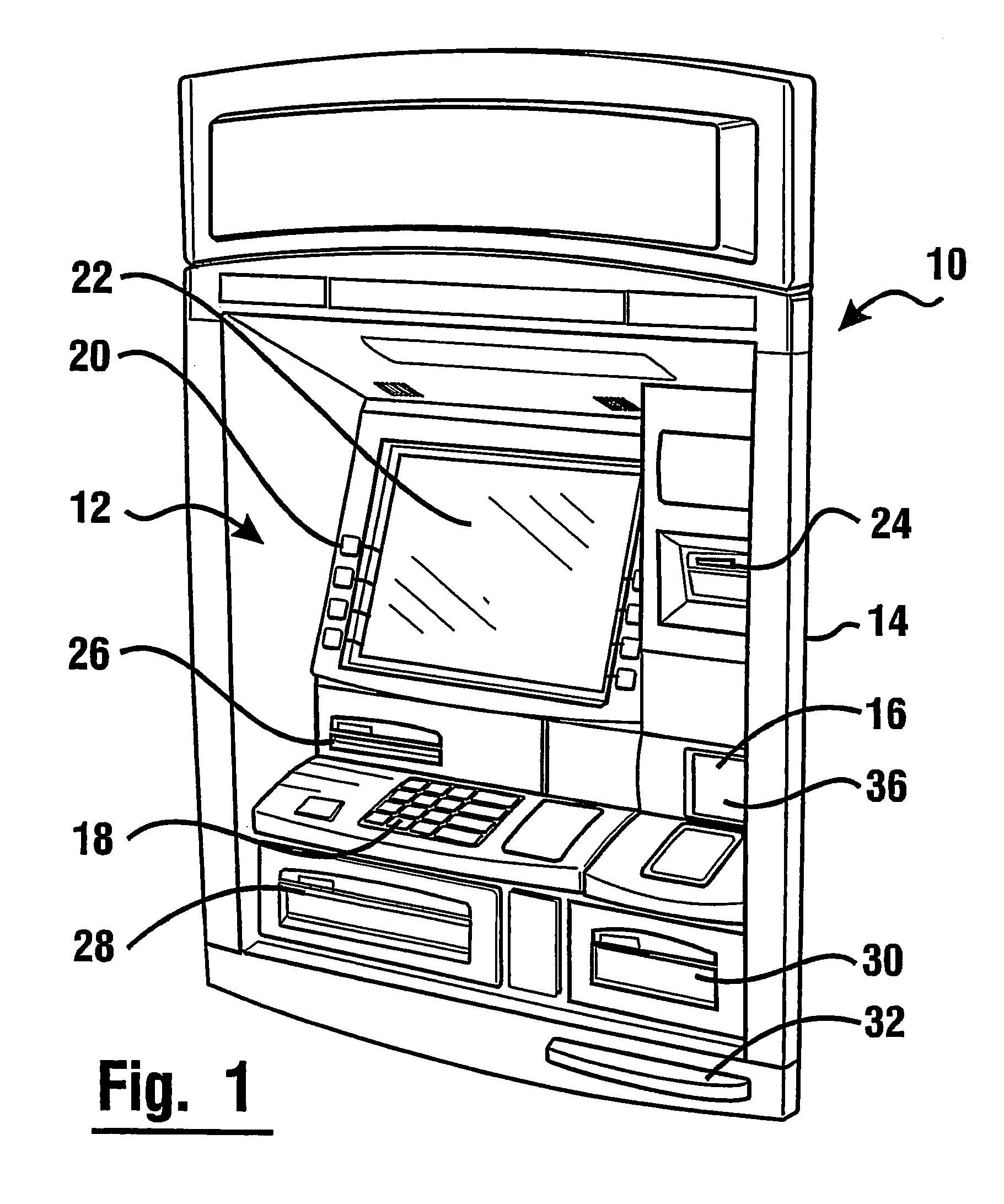
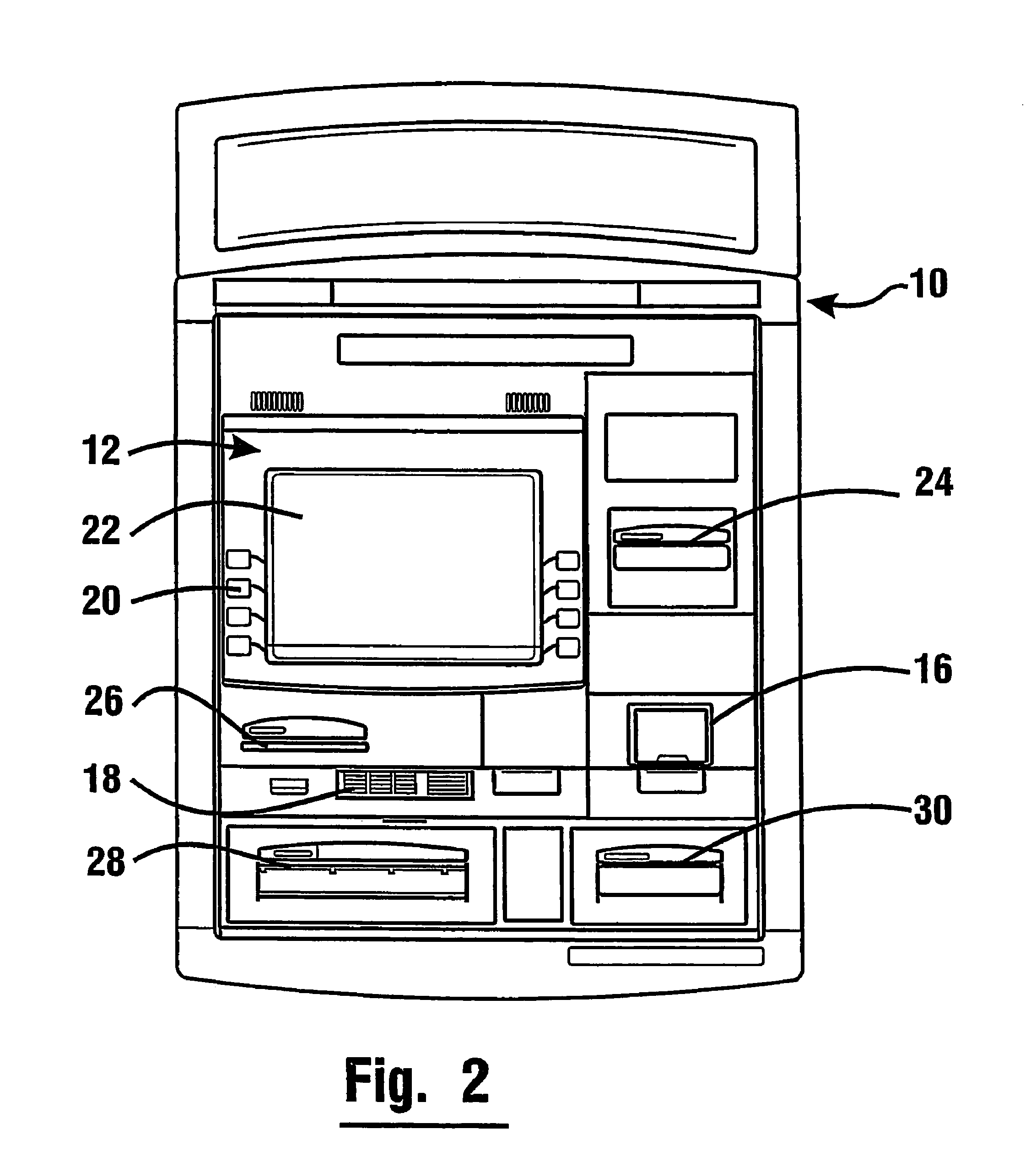
[0034]Referring now to the drawings and particularly to FIG. 1 there is shown therein an automated banking machine, generally indicated by numeral 10, used in connection with exemplary embodiments. A banking system that is controlled by data bearing records includes the automated banking machine 10. The automated banking machine 10 can be an automated teller machine (ATM). The ATM can include one or more cash dispensers. A cash dispenser includes one or more mechanisms that operate to selectively dispense cash stored within the machine to users of the machine. The automated banking machine 10 includes a fascia 12 which serves as a user interface (or customer interface).

[0035]The automated banking machine 10 includes a housing 14 which houses certain components of the machine. The components of the machine can include input and output devices. The input devices may include a reader device schematically indicated 16. The reader device is operative to read data bearing records presente...


PUM


Abstract

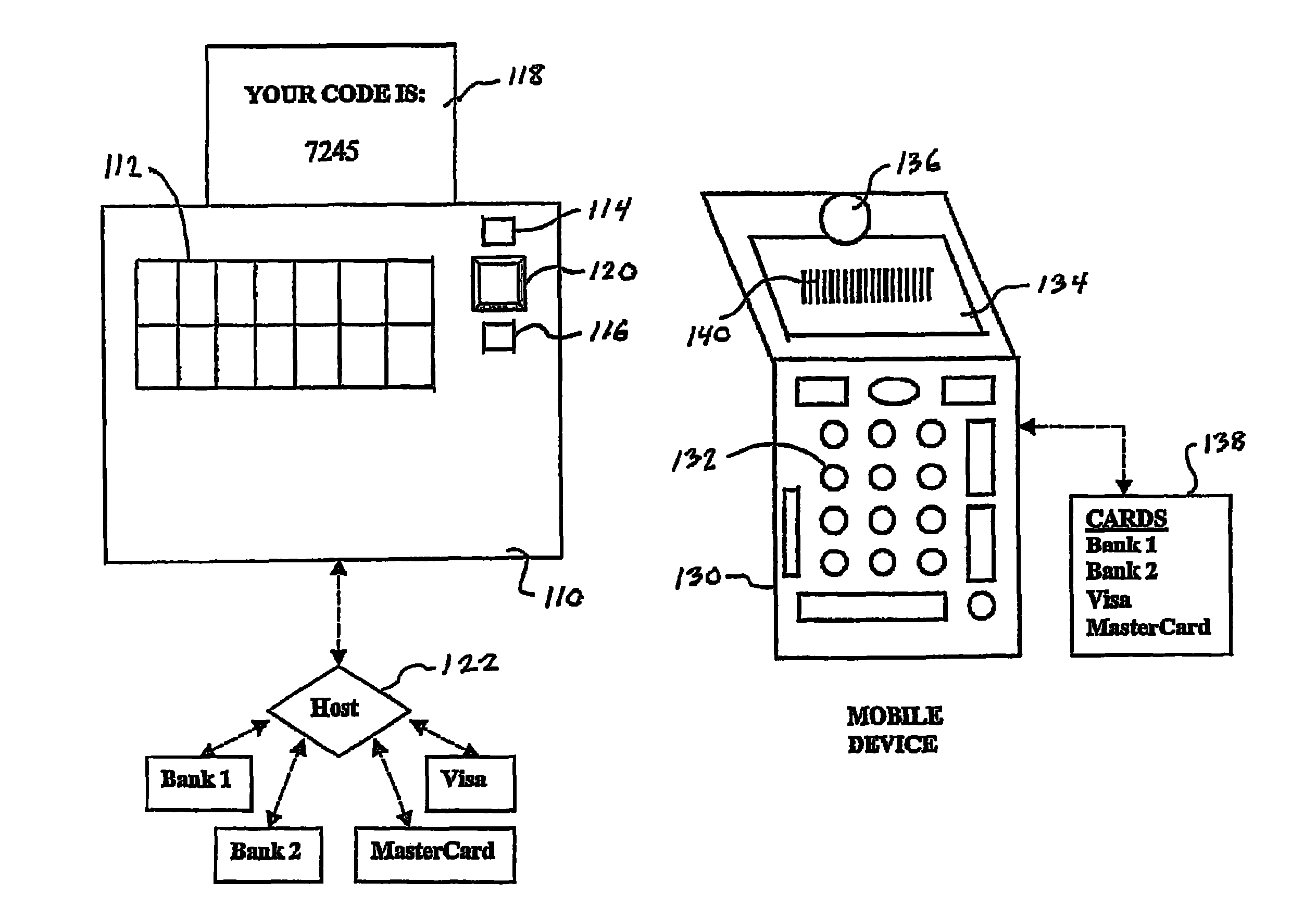
An automated banking machine can receive user card data from a cell phone. The phone stores the card data of several selectable cards, including electronic account number data. The machine generates and displays a random number correlated with a time period. A machine user manually inputs the displayed random number into their phone. A software application in the phone encrypts the selected card data along with the inputted random number data. The phone displays a bar code image containing the encrypted data. The banking machine includes a bar code reader which can read the displayed image. The machine causes the read data to be decrypted. The random number is used to verify the current transaction session. Thereafter, the user may provide other inputs, including PIN input. The process replaces physical insertion of a card yet allows secure input of the card data. Possible data interception from activities requiring card insertion are also reduced.

Description

CROSS REFERENCE TO RELATED APPLICATIONS[0001]This application is a continuation-in-part of U.S. application Ser. No. 11 / 975,907 filed Oct. 22, 2007. U.S. application Ser. No. 11 / 975,907 claims the benefits of U.S. Provisional Applications 60 / 918,453, 60 / 918,455, and 60 / 918,458 each filed Mar. 16, 2007; and application Ser. No. 11 / 975,907 is a continuation-in-part of U.S. application Ser. No. 11 / 093,741 filed Mar. 29, 2005, now U.S. Pat. No. 7,284,692, which claims the benefit of U.S. Provisional Application 60 / 557,937 filed Mar. 31, 2004. The disclosures of each of these applications are herein incorporated by reference.TECHNICAL FIELD[0002]This invention relates to banking systems controlled by data bearing records classified in U.S. Class 235 Subclass 379. Exemplary embodiments include card-activated automated banking machine apparatus, systems, and methods that provide improved security, reliability, and serviceability.BACKGROUND OF INVENTION[0003]Automated transaction machines i...

Claims


Application Information

Patent Timeline
Patent Type & Authority Patents(United States)
IPC IPC(8): G06Q40/00G07D11/00G07F19/00
CPCG06K7/0004G06Q20/102G06Q20/105G06Q20/1085G06Q20/32G06Q20/3227G06Q20/3274G06Q20/352G06Q20/385G06Q30/0237G06Q30/04G07F7/10G07F7/1075G07F19/20G07F19/205G06Q20/308G06Q20/326
Inventor RAMACHANDRAN, NATARAJANDOUGLASS, MARK A.
Owner DIEBOLD SELF SERVICE SYST DIV OF DIEBOLD NIXDORF INC
Learn More