
Current-mode dual-slope temperature-digital conversion device

a conversion device and current-mode technology, applied in the field of conversion devices, can solve the problems of increasing the time and cost of development, consuming more power, and affecting the portability of products, and achieve the effect of avoiding the curvature effect and high precision of a high linear relationship

Inactive Publication Date: 2012-03-27
NAT CHIAO TUNG UNIV
View PDF10 Cites 7 Cited by
  • Summary
  • Abstract
  • Description
  • Claims
  • Application Information

AI Technical Summary

Benefits of technology

"The present invention proposes a current-mode dual-slope temperature-digital conversion device that uses a dual-slope approach to achieve high precision and avoids the curvature effect. The device includes a current-type integrator and a small-size, power-saving, and less sensitive to temperature inverter, which replaces the conventional comparator. The device also includes a trigger and a logical controller that receives the first digital signal and outputs the second digital signal based on the switching state of the second switch and the first digital signal. The device further includes a time-digital converter that generates an output digital value based on the second digital signal and the clock signal. The technical effects of the invention include high precision, compactness, and high power efficiency."

Problems solved by technology

The complicated calibration circuit should increase the time and cost of development, consume more power, and impair portability of products.
However, the time-domain system has some problems in the curvature of the conversion curve because the time-domain system adopts an inverter or a delay element as the temperature-dependent sensor.

Method used


Image

  • Current-mode dual-slope temperature-digital conversion device
  • Current-mode dual-slope temperature-digital conversion device
  • Current-mode dual-slope temperature-digital conversion device

Examples


Embodiment Construction

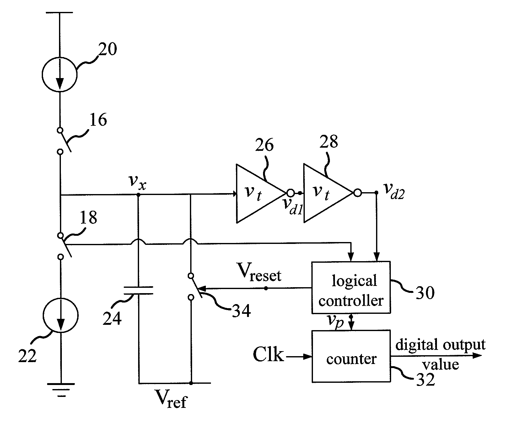
[0015]Refer to FIG. 2. The current-mode dual-slope temperature-digital conversion device of the present invention comprises a first switch 16 and a second switch 18, which are controlled by a group of non-overlapped control signals. When the first switch 16 is turned on, the second switch 18 is turned off. When the first switch 16 is turned off, the second switch 18 is turned on. Alternatively, the first and second switches 16 and 18 can be turned off simultaneously, but they cannot be turned at the same time. The first switch 16 and the second switch 18 are respectively connected with a reference current source 20 and a temperature-dependent current source 22. Both the reference current source 20 and the temperature-dependent current source 22 are direct current sources. The reference current source 20 generates a reference current. The temperature-dependent current source 22 generates a temperature-dependent current proportional to the temperature. The higher the temperature, the ...


PUM


Abstract

A current mode dual-slope temperature-to-digital conversion device is disclosed. The conversion device comprises a temperature dependent current source and a reference current source. Firstly, a capacitor is charged by the temperature dependent current source. Next, the capacitor is discharged by the reference current source. The capacitor is coupled to at least one trigger, and the trigger sends out a first digital signal to a logic controller by the voltage of the capacitor. Then, the logic controller sends out a second digital signal to a time-to-digital converter according to the first digital signal. When the capacitor is discharged by the reference current source and before the first digital signal is varied, the converter receives the second digital signal and a clock signal to generate a corresponding digital output value. The present invention achieves the requirement of the high linearity resolution with the dual-slope architecture lest the curvature effect resulted from the time-domain circuit be occurred.

Description

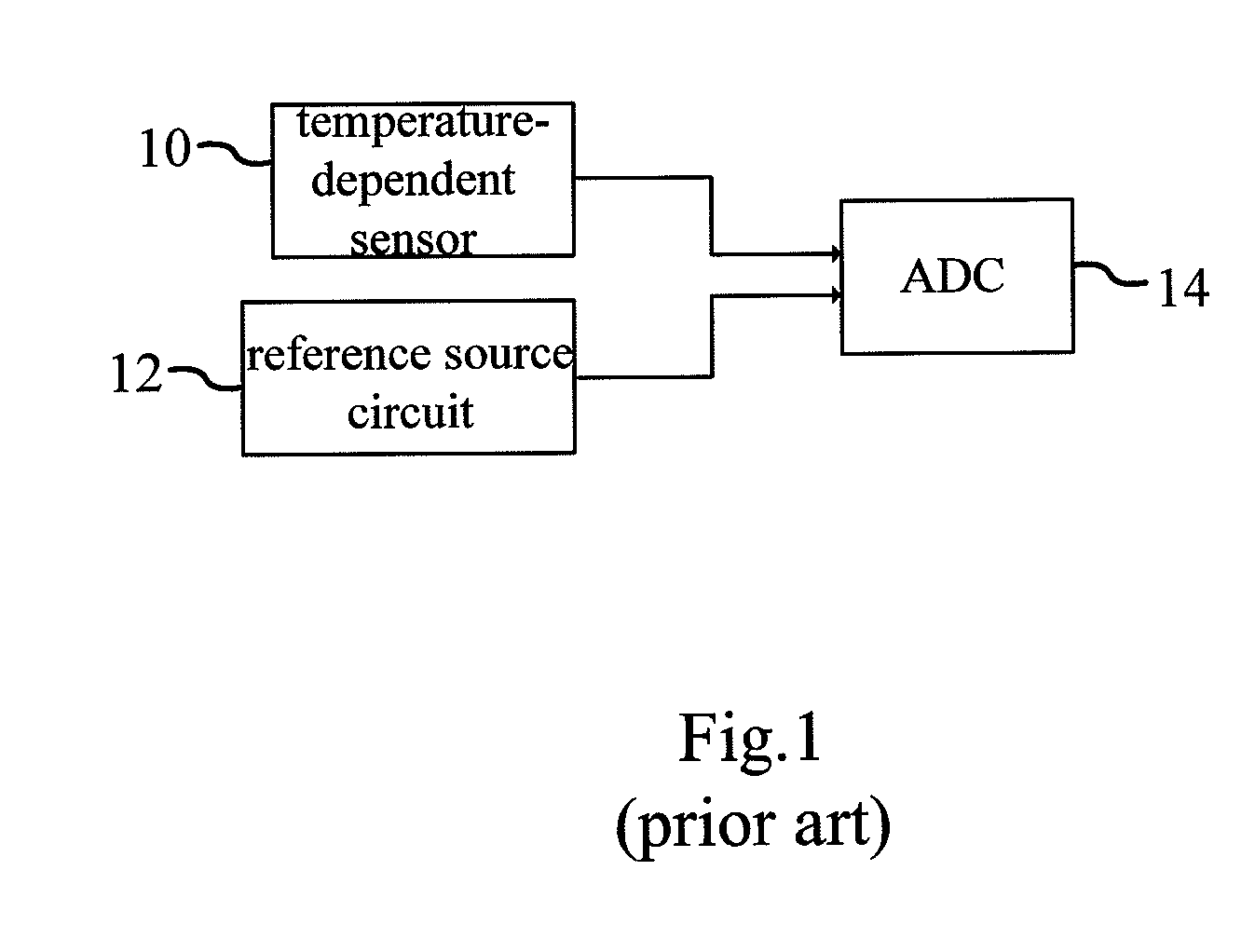
BACKGROUND OF THE INVENTION[0001]1. Field of the Invention[0002]The present invention relates to a conversion device, particularly to a current-mode dual-slope temperature-digital conversion device.[0003]2. Description of the Related Art[0004]The daily-life appliances usually need temperature data, such as air conditioners, refrigerators, and fire warning systems. Temperature is measured via detecting the variation of a physical property, such as resistance variation, color variation, volume variation or electromotive force generated by magnetic flux change. The electric conductivity of a semiconductor material is greatly influenced by temperature. Therefore, the electric conductivity of an integrated circuit made of semiconductor materials correlates with temperature. The temperature characteristic curve of an integrated circuit is thus used to fabricate a temperature-sensing integrated circuit.[0005]Refer to FIG. 1. A general temperature sensor comprises a temperature-dependent se...

Claims


Application Information

Patent Timeline
Patent Type & Authority Patents(United States)
IPC IPC(8): H03M1/82
CPCH03M1/52
Inventor LIN, MING-TSEHUNG, CHUNG-CHIH
Owner NAT CHIAO TUNG UNIV
Learn More