
Charge control device and vehicle using the same

a control device and a technology for vehicles, applied in the direction of electric devices, machines/engines, process and machine control, etc., can solve the problems of motor generation torque, increased ripple influence to the input side, only utilizing leakage inductance, etc., to achieve sufficient inductance and reliably prevent the movement of the vehicle

Active Publication Date: 2012-03-27
TOYOTA JIDOSHA KK
View PDF15 Cites 7 Cited by
  • Summary
  • Abstract
  • Description
  • Claims
  • Application Information

AI Technical Summary

Benefits of technology

The present invention provides a charge control device for vehicles that can attain sufficient inductance and prevent movement of the vehicle when a power storage device is charged from an external power supply. The device includes an AC rotating electric machine, an inverter, a connecting device, a rotation angle detecting device, and an inverter control unit. The invention also provides a vehicle with this charge control device and a gear mechanism. The technical effects of the invention include preventing power loss during charging, ensuring reliable vehicle movement, and reducing rotation resistance of the output shaft of the internal combustion engine.

Problems solved by technology

When equal currents are caused to flow through three-phase coils of the motor, however, what can be utilized is only the leakage inductance of the coil.
Therefore, there may be problems that the commercial power supply cannot sufficiently be boosted to the battery voltage, or influence of ripple to the input side increases.
Further, when the one-phase coil or two-phase coils are selected and a current is caused to flow therein, the motor generates torque and, possibility of the vehicle moving during charging cannot perfectly be eliminated.

Method used


Image

  • Charge control device and vehicle using the same
  • Charge control device and vehicle using the same
  • Charge control device and vehicle using the same

Examples


embodiment 1

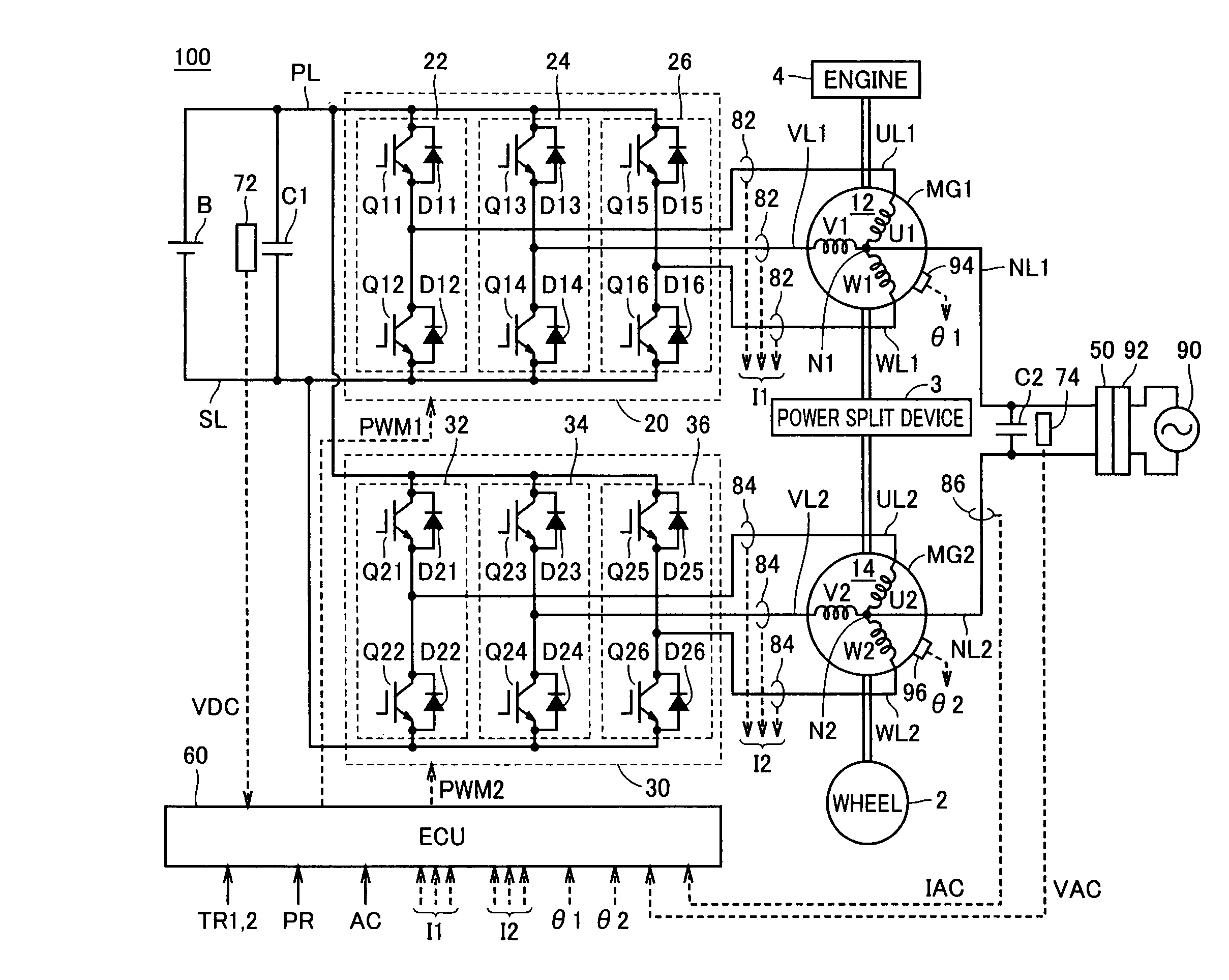
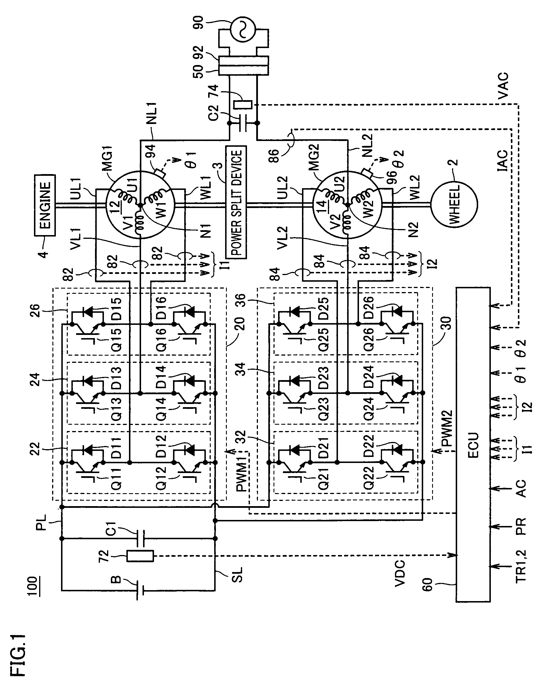
[0041]FIG. 1 is an overall block diagram of the hybrid vehicle shown as an example of the vehicle in accordance with Embodiment 1 of the present invention. Referring to FIG. 1, a hybrid vehicle 100 includes an engine 4, motor generators MG1 and MG2, a power split device 3, and wheels 2. Hybrid vehicle 100 further includes a power storage device B, inverters 20 and 30, and an ECU (Electronic Control Unit) 60.

[0042]Hybrid vehicle 100 further includes a capacitor C1, a power line PL, a ground line SL, U-phase lines UL1 and UL2, V-phase lines VL1 and VL2, W-phase lines WL1 and WL2, a voltage sensor 72, current sensors 82 and 84 and resolvers 94 and 96. Hybrid vehicle 100 further includes power lines NL1 and NL2, a connector 50, a capacitor C2, a voltage sensor 74, and a current sensor 86.

[0043]Hybrid vehicle 100 runs using engine 4 and motor generator MG2 as power sources. Power split device 3 is coupled to engine 4 and to motor generators MG1 and MG2, and distributes power among these....

embodiment 2

[0100]In Embodiment 1, during charge control, only one phase of inverter 20 is controlled to attain large conductance, and motor generator MG2 is caused to generate a torque that cancels out the torque generated by motor generator MG1.

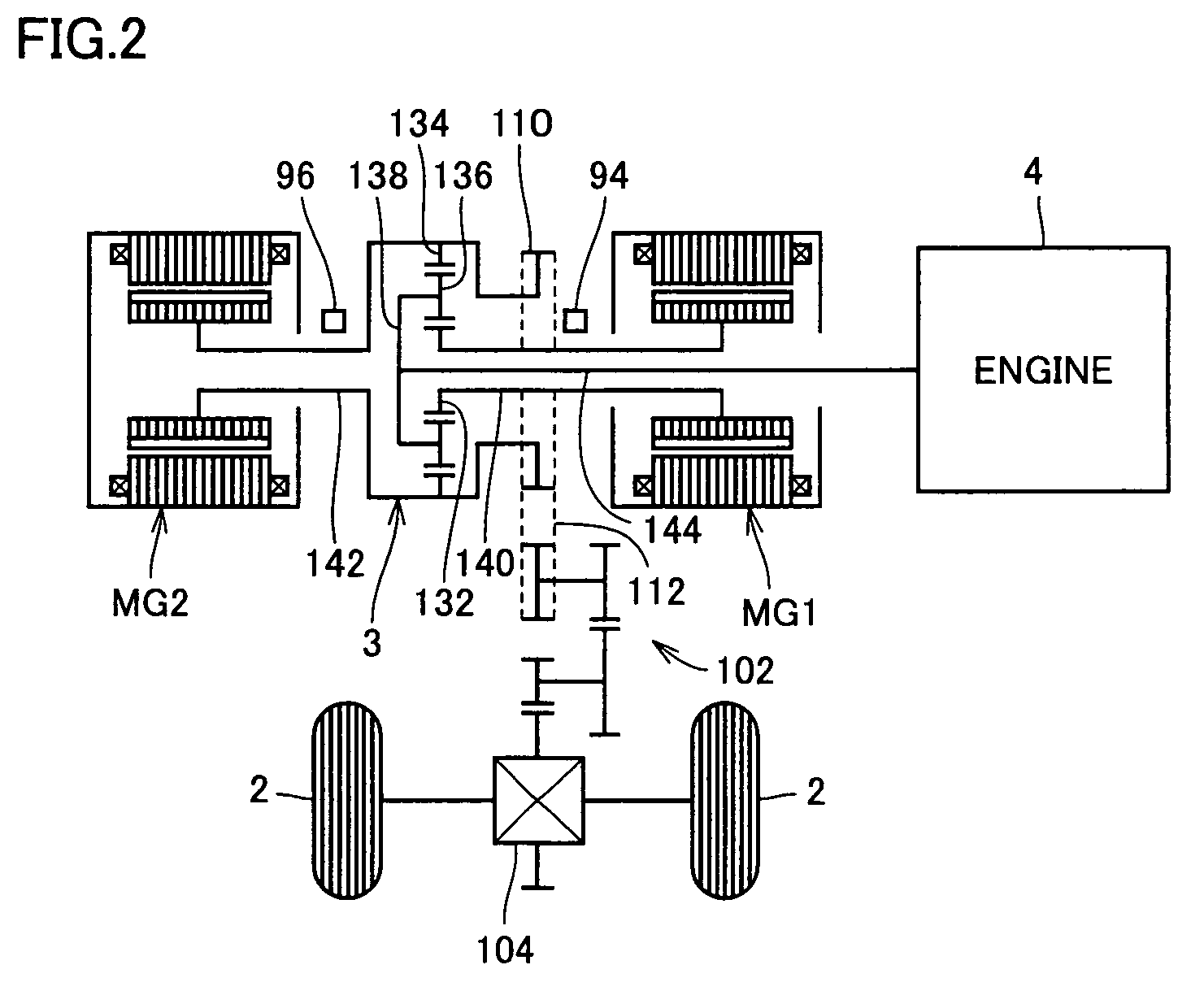
[0101]In Embodiment 2, during charge control, rotation resistance of engine 4 is lowered, so that the torque generated by motor generator MG1 is not transmitted through power split device 3 to the driving shaft. Therefore, rotation resistance of carrier shaft 144 coupled to engine 4 is reduced, and even if sun gear shaft 140 coupled to motor generator MG1 rotates, carrier shaft 144 rotates accordingly and, therefore, transmission of the torque to ring gear shaft 142 coupled to the vehicle driving shaft can be prevented.

[0102]FIG. 7 is a flowchart representing the charge control in accordance with Embodiment 2. Referring to FIG. 7, ECU 60 determines whether charge control is in progress or not based on the signal AC (step S110). If it is determined that...

embodiment 3

[0107]In Embodiment 3, a clutch is provided between carrier shaft 144 and engine 4, and at the time of charge control, the clutch is set to a disengaged state, to reduce rotation resistance of carrier shaft 144.

[0108]FIG. 8 shows a schematic configuration of a power output mechanism in the hybrid vehicle in accordance with Embodiment 3. Referring to FIG. 8, the power output mechanism in accordance with Embodiment 3 corresponds to the configuration shown in FIG. 2 and additionally includes a clutch 150 and a clutch actuator 152.

[0109]Clutch 150 is arranged between a crankshaft 115 of engine 4 and carrier shaft 144. Clutch actuator 152 engages and disengages clutch 150, based on a signal CR from ECU 60, not shown. Specifically, when the signal CR is active, clutch actuator 152 sets clutch 150 to the disengaged state, and when the signal CR is inactive, it sets clutch 150 to the engaged state.

[0110]In Embodiment 3, during charge control, the signal CR is activated and clutch 150 is set...


PUM


Abstract

At the time of charging a power storage device from a commercial power supply, electric power from the commercial power supply is applied to a neutral point of each of first and second motor generators. A rotation preventing control unit (222) determines one phase to be subjected to switching control in the first inverter, based on a rotation angle (θ1) of the first motor generator. Further, rotation preventing control unit (222) calculates torque generated in the first motor generator, generates a torque control value for canceling out the torque, and outputs the value to a phase voltage operating unit (214) for motor control.

Description

TECHNICAL FIELD[0001]The present invention relates to a charge control device and a vehicle provided with the charge control device and, more specifically, to a charge control device for charging a power storage device mounted on a vehicle from a commercial power supply and to a vehicle provided with the charge control device.BACKGROUND ART[0002]Japanese Patent Laying-Open No. 8-126121 discloses a charging apparatus mounted on an electric vehicle. The charging apparatus mounted on a vehicle includes two permanent magnet motors, two inverters provided corresponding to respective motors, a battery, a connecting circuit connecting a commercial power supply to a neutral point of each motor, and a control circuit charging the battery from the commercial power supply by causing equal currents to three-phase coils of the motors.[0003]In the charging apparatus mounted on a vehicle, equal currents are caused to flow through three-phase coils of the motors and, therefore, generated magnetic f...

Claims


Application Information

Patent Timeline
Patent Type & Authority Patents(United States)
IPC IPC(8): H02J7/00B60W20/00F01L1/12B60K6/445B60L50/15B60L50/16B60W10/08B60W10/26H02P3/02
CPCB60K6/445B60L11/123B60L11/14B60L11/1811B60L11/1812B60L11/1814B60L11/1816B60L15/007B60W10/06B60W10/08B60W10/26B60W20/00B60K6/365B60K1/02Y10S903/906B60L2220/14B60L2220/54B60L2240/423B60W2710/083Y02T10/6217Y02T10/6269Y02T10/6286Y02T10/641Y02T10/642Y02T10/7005Y02T10/7077Y02T90/127Y02T90/14Y02T10/6239Y02T10/7072B60L53/14B60L53/22B60L50/61B60L50/16B60L53/20B60L53/24Y02T10/62Y02T10/64Y02T10/70B60W20/13Y02T90/12
Inventor OYOBE, HICHIROSAIISHIKAWA, TETSUHIRONAKAMURA, MAKOTOMINEZAWA, YUKIHIRO
Owner TOYOTA JIDOSHA KK
Learn More