
Display panel, method for producing the same and composition of ink used by the method for producing the same

a technology for display panels and inks, applied in the field of display panels, can solve the problems of low printing position or resolution accuracy, increase in the number of processing steps or processing time, and limitation of applicable designs, and achieve the effects of less yellowing, good storage stability, and rapid polymerization ra

Active Publication Date: 2012-03-27
DENSO CORP +1
View PDF16 Cites 1 Cited by
  • Summary
  • Abstract
  • Description
  • Claims
  • Application Information

AI Technical Summary

Benefits of technology

[0025]The present invention has been made in view of such conventional problems, and thus, it is an object of the present invention to provide a display panel capable of coping with various designs and molding processing, and a method for producing the display panel.

Problems solved by technology

Thus, there is a problem that the number of processing steps or the processing time may be increased.
Furthermore, the screen printing method has a problem that there is limitation in the applicable designs, because accuracy of the printing position or resolution is generally low.
Since it is required in the screen printing method to go through the procedure of replacing the plate and inks, setting the printing conditions and the like, whenever the type of the display panel is changed, there is a problem of an increase in the costs.
In addition, the screen printing method, which is a mass printing technique, is not suitable for manufacturing a small quantity of products such as trial products or supply products.
In other words, there is a problem that processes such as plate making and lithographic plate making, which are incidental to the method, add to an increase in the costs.
However, employing the inkjet method in the formation of a printed layer of the display panel faced the following problems.
However, when inkjet printing is performed on such material using an aqueous ink, ink droplets spatter on the surface, while in the case of a solvent-based ink, there is a risk that ink droplets aggregate before they dry, or the ink droplets dissolve the substrate, thus resulting in substrate deformation.
If a display panel is produced using an ink having insufficient stretchability and adhesiveness, there is a risk of cracks occurring in the printed layer at the time of subjecting the display panel to molding by means of a mold having a predetermined shape, or to punching processing, cutting processing or the like.
However, the UV-curable inks that are currently under development, are inks having excellent stretchability and adhesiveness but insufficient curability, or inks having excellent curability but insufficient stretchability and adhesiveness.
Since the combination of stretchability and adhesiveness, and curability are generally properties conflicting with each other, it has been very difficult to develop an ink having the properties of both sides to very high levels.
However, if an ink having curability so high to the extent of preventing cracks upon pressing is used, the stretchability and adhesiveness are impaired.
Therefore, in this case, there is a problem that molding and processing of the display panel become difficult.
In other words, there has been a need to reduce the amount of molding or the amount of processing, or to design the display panel not to have a printed layer provided at the pressed part, thereby limitation being imposed on the design of display panels.
On the other hand, the UV-curable inks that are currently under development have excellent stretchability and adhesiveness, but on the other hand, have a problem of insufficient curability.
For that reason, with regard to the display panel produced using such a UV-curable ink, there is a risk that tackiness may still remain at the surface of the printed layer even after the ink has been cured, and have deteriorated durability of the printed layer.
Specifically, there is a risk that, for example, the ink may leave marks when there occurs a contact with the printed layer after curing, or that if a display panel having the printed layer formed therein is stored in piles, the display panels may adhere to each other through the printed layer, or the printed layer may be transferred to the display panel.
However, the inks having excellent curability have insufficient stretchability and adhesiveness.
For that reason, in the display panels produced using such UV-curable inks, there is a risk that cracks may be generated in the printed layer when the display panel is subjected to molding by means of a mold having a predetermined shape, or subjected to punching processing, cutting processing or the like.
Also, at the time of applying a casing, there is a risk that cracks may be generated in the printed layer because of the stress exerted on the fitting part of the display panel and the casing of the display device or the like.

Method used


Image

  • Display panel, method for producing the same and composition of ink used by the method for producing the same
  • Display panel, method for producing the same and composition of ink used by the method for producing the same
  • Display panel, method for producing the same and composition of ink used by the method for producing the same

Examples


embodiment 1

[0190]In the present embodiment, as shown in Table 1, a plurality of UV-curable inks having different compositions were prepared, and these were used in printing on a resin substrate to evaluate the characteristics as the inks for display panels.

[0191]First, as shown in the following Table 1, a plurality of UV-curable inks having different compositions (sample X1 to sample X3) was prepared.

[0192]These inks respectively contain a monofunctional monomer, a polyfunctional monomer (bifunctional monomer) and a pigment in the composition shown in Table 1. Each ink also contains a polymerization initiator, a dispersant and the like in addition to them. The components other than the UV-curable monomers and the pigment were contained in almost the same amount in each of the inks.

[0193]Next, a resin substrate formed from polycarbonate and having a thickness of 0.5 mm was provided. Printing was performed on this resin substrate by inkjet printing, using each of the UV-curable inks (samples X1 ...

embodiment 2

[0264]In the present embodiment, as shown in Table 3 to Table 8, a plurality of UV-curable inks having different compositions were first prepared, and an evaluation thereof as inks for the use in a display panel was performed.

[0265]First, UV-curable inks having a composition falling in the scope of the present invention (Examples 1 to 19), and UV-curable inks having compositions out of the scope of the present invention (Comparative Examples 1 to 8) were prepared. The composition of the UV-curable monomers in the UV-curable ink and the viscosity of the UV-curable ink are presented in Tables 3 to 8.

[0266]These inks (Examples 1 to 19 and Comparative Examples 1 to 8) contain a monofunctional monomer, a bifunctional monomer, a pigment, as well as a polymerization initiator and a dispersant. The types and contents of the components other than the UV-curable monomers and the pigment are respectively the same and almost equal for the various inks.

[0267]Subsequently, a resin substrate forme...

embodiment 3

[0306]The present embodiment is an example for producing an instrument dial plate for vehicles, as the display panel.

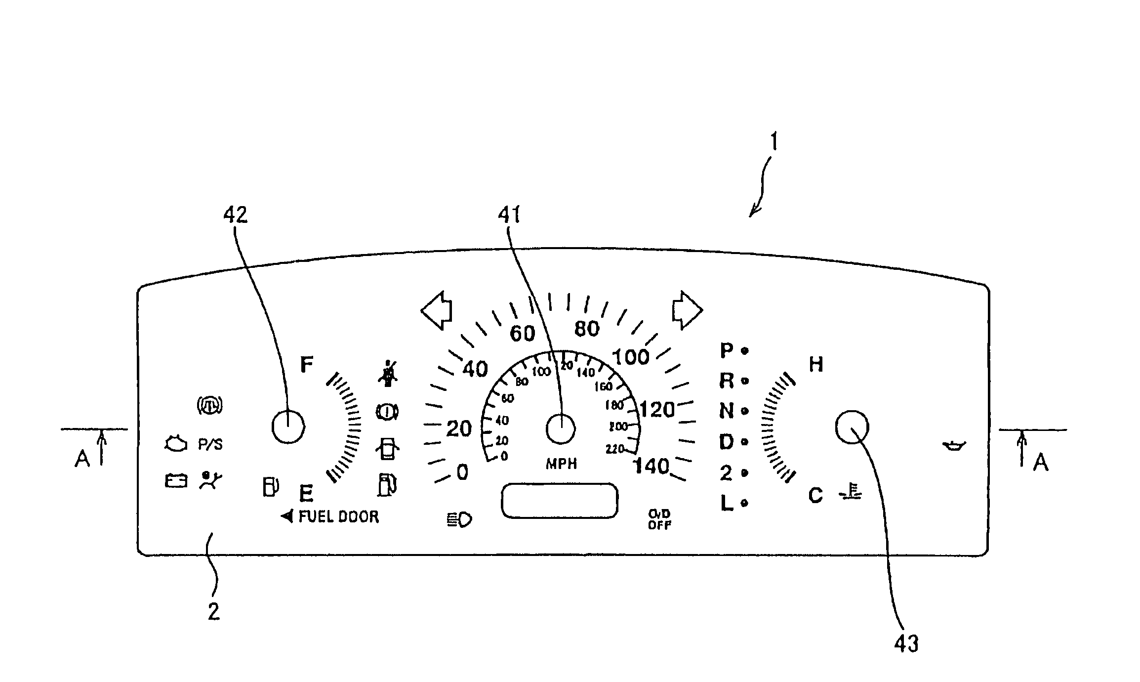
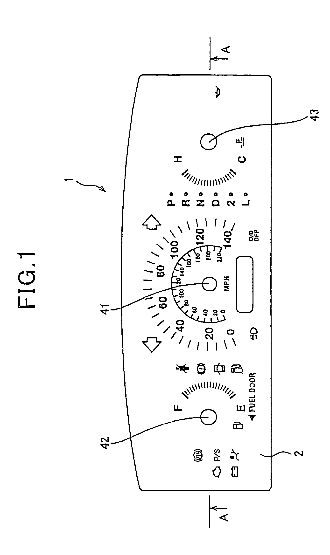
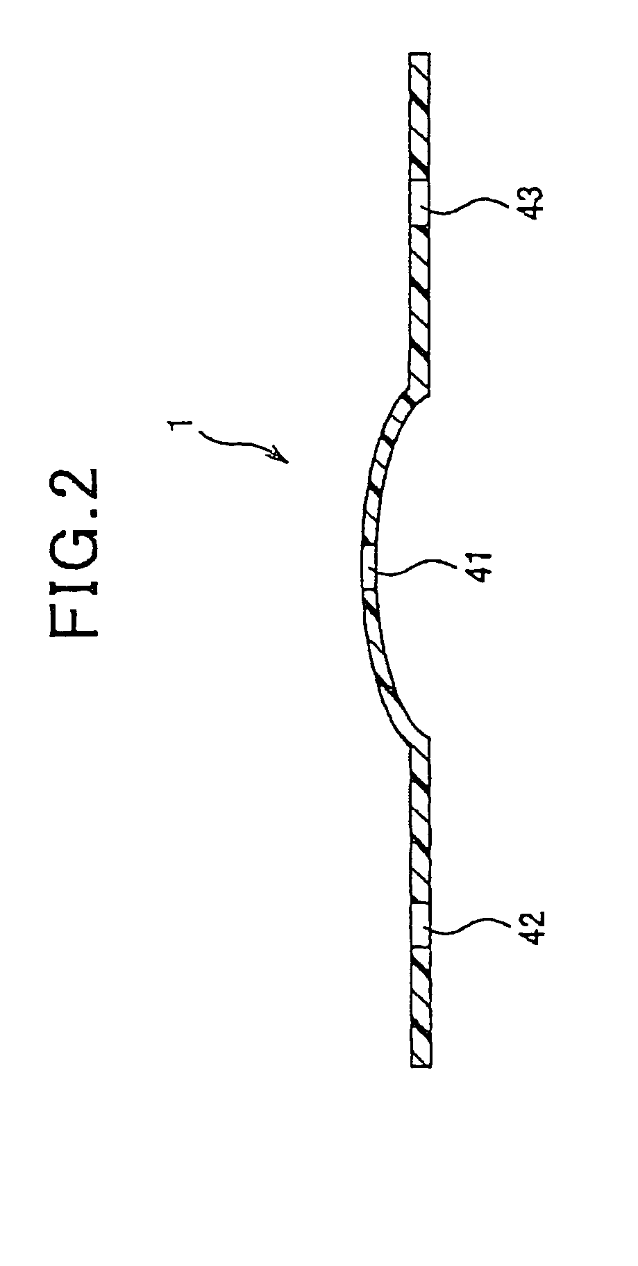
[0307]As shown in FIGS. 1, 2 and 10, the display panel 1 of the present Example has a resin substrate 15, and printed layers 21, 22 and 23 formed thereon by performing inkjet printing using a UV-curable ink, and curing the UV-curable ink.

[0308]As shown in FIG. 1 and FIG. 2, the display panel 1 of the present Example is an instrument dial plate for vehicles. FIG. 1 is a front view of the display panel 1 of the present Example. FIG. 2 is a cross-sectional view of the display panel 1 shown in FIG. 1. The display panel 1 has been subjected to molding processing, and thus has a structure in which the central part is more protruded than the periphery. FIG. 10 shows a cross-sectional view of the display panel 1 before it has been subjected to molding processing.

[0309]The display panel 1 has a light transmissive resin substrate 15, and printed layers 21, 22 and 23 formed by l...


PUM

PropertyMeasurementUnit
weight ratioaaaaaaaaaa
particle sizeaaaaaaaaaa

Abstract

A display panel has a resin substrate and a printed layer formed on at least a part of the resin substrate through inkjet printing. The printed layer is formed from cured products of UV-curable inks each containing UV-curable monomers which are polymerized and cured by UV irradiation, and the printed layer has at least two such cured products having different pencil hardness values.

Description

CROSS REFERENCES TO RELATED APPLICATION[0001]The present application relates to and incorporates by reference Japanese Patent application No. 2007-222520 filed on Aug. 29, 2007 and Japanese Patent application No. 2007-268987 filed on Oct. 16, 2007.BACKGROUND OF THE INVENTION[0002]1. Field of the Invention[0003]The present invention relates to a display panel used in, for example, the display devices for instrument gauges equipped in a vehicle or the like, and a method for producing the display panel.[0004]2. Description of the Related Art[0005]Conventionally, vehicles such as automobiles for example, are provided with an arrangement of display devices for instrument gauges in the dashboard facing the driver's seat. In general, as set forth in Japanese Patent Laid-open (unexamined) No. 2001-343260, a display device for vehicles (automotive instrument panel) includes a display panel having graphical design parts (printed layer) containing scales, characters and the like, and a light s...

Claims


Application Information

Patent Timeline
Patent Type & Authority Patents(United States)
IPC IPC(8): B41M5/40
CPCB60K37/02G01D13/20G01D11/28B60K2350/1064B60K2350/203Y10T428/24802B41M5/0023B60K2370/154B60K2370/33
Inventor IWASE, TERUHIKOAOKI, TAKASHIINA, OSAMUYOSHIHIRO, YASUOTAKAHASHI, YUKITOSHISATO, SHINICHI
Owner DENSO CORP
Learn More