
Differential receiver with frequency offset compensation

a receiver and frequency offset technology, applied in the field ofdifferential receivers, can solve the problems of significant performance loss, difficult to accurately extract data payload, communication system suffer, etc., and achieve the effect of widening the estimation range of frequency offset, reducing computation complexity, and chip area and power consumption

Active Publication Date: 2012-03-20
NXP USA INC
View PDF22 Cites 5 Cited by
  • Summary
  • Abstract
  • Description
  • Claims
  • Application Information

AI Technical Summary

Benefits of technology

The present invention addresses the problems of conventional receivers by estimating and tracking frequency offset in the phase domain. This reduces computational complexity, chip area, and power consumption. The initial estimate of frequency offset can be acquired with a few pilot symbols, and tracking ensures accurate estimation even in the presence of fading channels or slowly-drifting frequency characteristics. The invention is a differential receiver that receives an RF signal and outputs the digital data payload. The RF signal is processed through differential detection to obtain demodulated signals from which phase is extracted. The initial estimate of frequency offset is acquired from the extracted phase, and the estimate is applied by the receiver in compensation of frequency offset. The compensated signal is thereafter processed, such as by demodulation, decoding, and bit slicing, so as to obtain the encoded digital data payload. The invention also includes methods for sharing already-existing components in the receiver and compensating for frequency offset in the time domain or phase domain. The invention can be implemented in hardware, software, or hybrid hardware / software systems.

Problems solved by technology

Such communication systems suffer, however, from significant performance loss introduced by frequency offset, since it is difficult to accurately extract the data payload from a received signal in the presence of frequency offset.
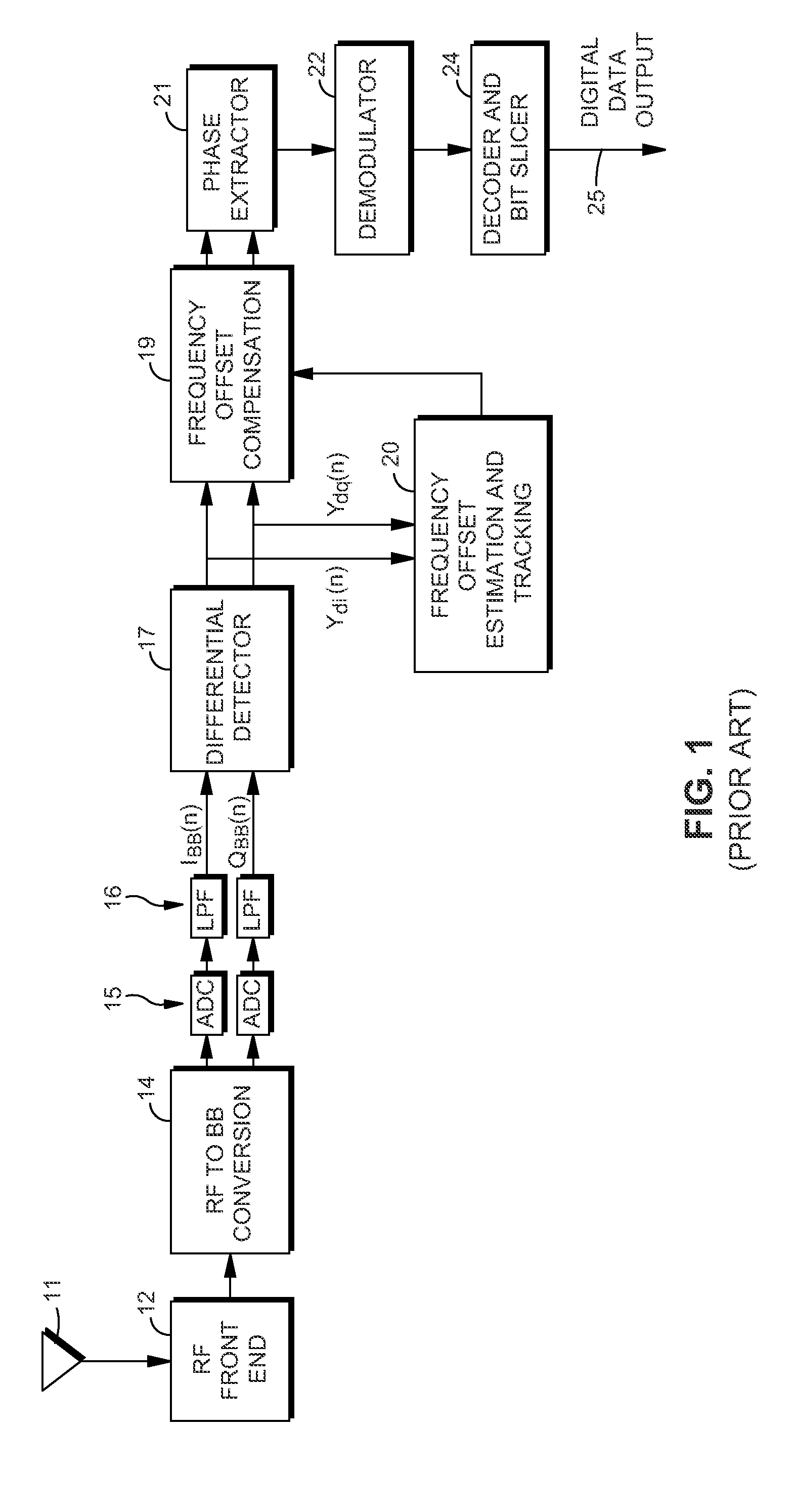
As shown above, in conventional receivers, the estimation and tracking of frequency offset is computationally expensive.
Thus, in terms of complexity, chip area and / or power consumption, the conventional technique for estimation and tracking of frequency offset has its disadvantages.
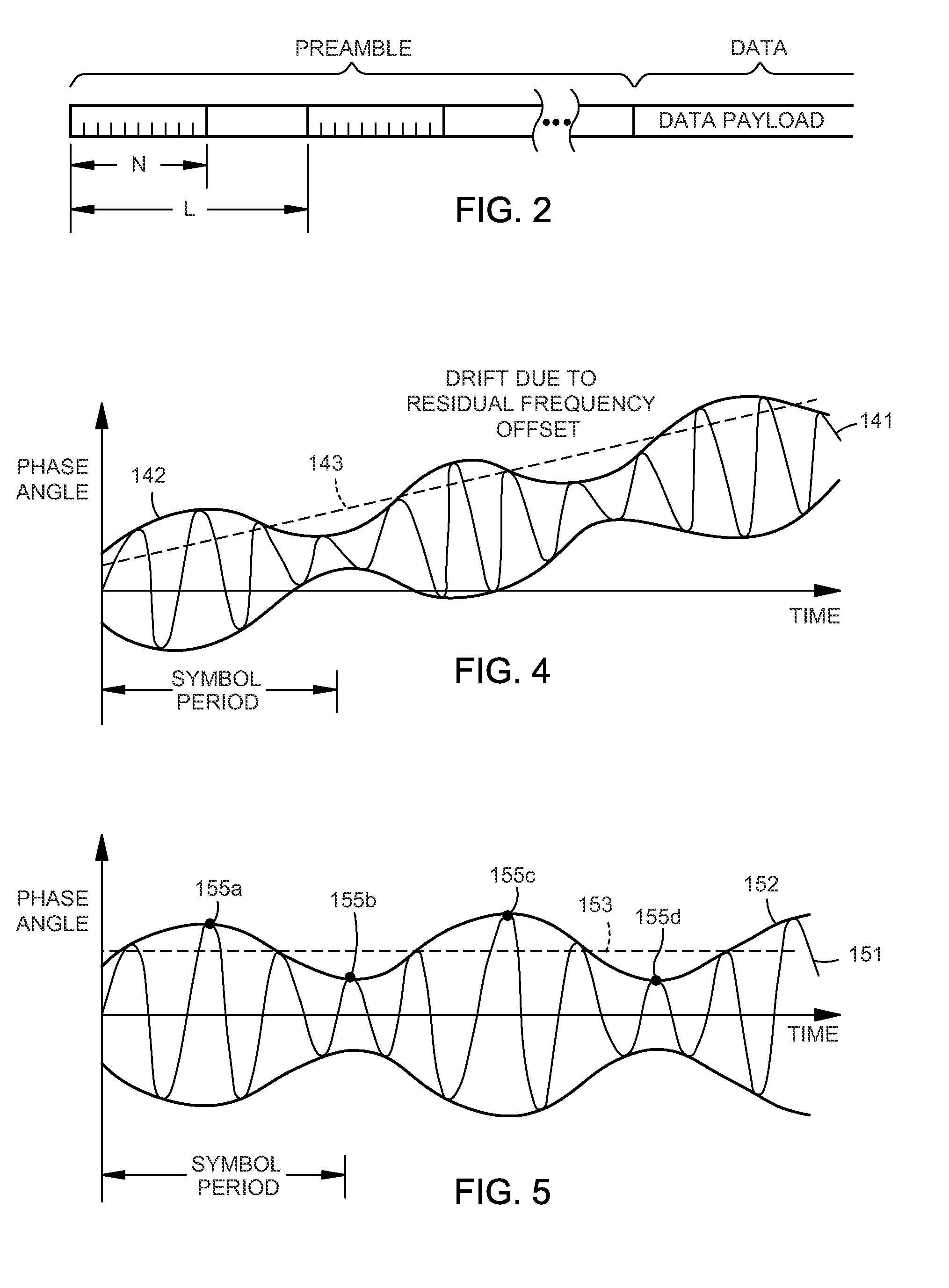
Since a large number of symbols N are needed, the value of L tends to increase, and conventional systems tend to exhibit a limited estimation range for estimation of frequency offset.

Method used


Image

  • Differential receiver with frequency offset compensation
  • Differential receiver with frequency offset compensation
  • Differential receiver with frequency offset compensation

Examples


first embodiment

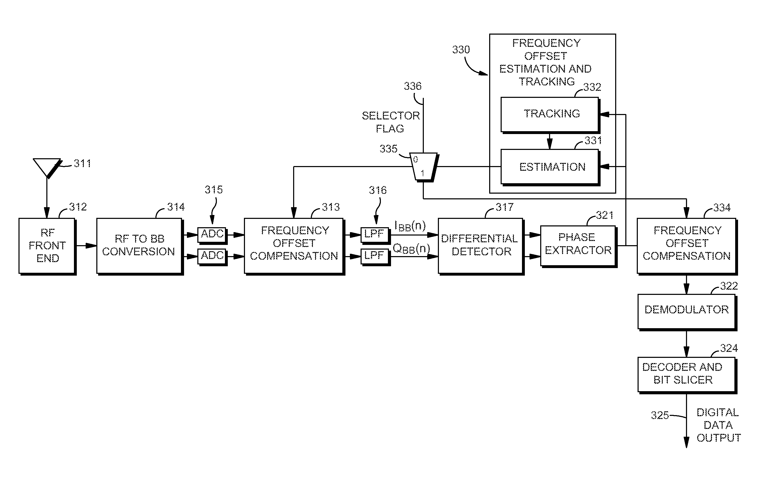
[0037]FIG. 3 is a block diagram showing the invention, in which frequency offset estimation and tracking are both performed in the phase domain, and in which compensation therefor is also applied in the phase domain.

[0038]As shown in FIG. 3, an RF signal encoding a data payload is received by antenna 111, processed by RF front end 112, and down-converted to a baseband signal by RF-to-BB converter 114. A pair of A-to-D converters 115 convert the analog signals from RF-to-BB converter 114 into digital data, which is thereupon supplied to a pair of low-pass filters 116 and thence to differential detector 117. The differential detector 117 accepts the in-phase and quadrature phase signals (IBB and QBB, respectively) from the low-pass filters 116, and applies differential detection thereto so as to obtain corresponding demodulated PSK signals which, again, may be expressed mathematically, as follows:

y(n)=ydi(n)+j*ydq(n)=aejψ  (Equation 1)

where y(n) is the nth symbol, ydi and ydq are the ...

second embodiment

[0049]FIG. 6 is a view showing the invention, in which frequency offset estimation and tracking is performed in the phase domain, as before, but in which compensation is performed in the time domain. Reference numerals shown in FIG. 6 are similar to those in FIG. 3 where functionality is also similar, and a description thereof is omitted.

[0050]Referring to FIG. 6, frequency offset compensation block 213 performs frequency offset compensation in the time domain. Compensation is performed based on an estimate obtained by frequency offset estimation and tracking block 230, which obtains its estimate of frequency offset in the phase domain in a manner similar to that of block 130 of the first embodiment.

third embodiment

[0051]the invention is shown in FIG. 7 in which there is a programmable selection as to whether frequency offset compensation is performed in the phase domain or in the time domain. Like-numbered reference numerals are used in FIG. 7 relative to FIGS. 3 and 6, for similarly-functioning blocks.

[0052]In FIG. 7, programmable selector 335 provides the estimate of frequency offset either to a time domain-based compensator 313 or to a phase domain-based compensator 334. Selection of the destination is programmable in accordance with selector flag 336.

[0053]FIG. 8 is a generalized flow diagram showing methods performed by the invention herein. The process steps shown in FIG. 8 may be carried out by a hardware apparatus embodying the invention, or they may be carried out by software embodying the invention, or in hybrid hardware / software systems. In the case of software, the software is ordinarily stored on computer-readable memory media such as ROM or EEPROM which stores computer-executabl...


PUM


Abstract

A differential receiver which provides for estimation and tracking of frequency offset, together with compensation for the frequency offset. Estimation and tracking of the frequency offset is undertaken in the phase domain, which reduces computational complexity and allows frequency offset estimation and tracking to be accomplished by sharing already-existing components in the receiver. Compensation for the frequency offset can be performed either in the time domain, before differential detection, or in the phase domain, after demodulation, or can be made programmably selectable, for flexibility.

Description

CROSS-REFERENCE TO RELATED APPLICATION[0001]The present application is a continuation of non-provisional application Ser. No. 11 / 500,633, filed Aug. 8, 2006, entitled “DIFFERENTIAL RECEIVER WITH FREQUENCY OFFSET COMPENSATION,” now U.S. Pat. No. 7,809,083, issued Oct. 5, 2010, which claims the benefit of U.S. Provisional Patent Application No. 60 / 761,241, filed Jan. 23, 2006, the entire specifications of which are hereby incorporated by reference in their entireties for all purposes, except for those sections, if any, that are inconsistent with this specificationBACKGROUND OF THE INVENTION[0002]1. Field of the Invention[0003]The present invention relates to a differential receiver which provides for estimation and / or tracking of frequency offset, together with compensation for the frequency offset.[0004]2. Description of the Related Art[0005]Differential receivers are popular in a variety of circumstances, such as in wireless local area networks (WLAN, for example, IEEE 802.11) or pe...

Claims


Application Information

Patent Timeline
Patent Type & Authority Patents(United States)
IPC IPC(8): H03D3/22
CPCH04L27/2332H03J7/02
Inventor WU, SONGPINGLOU, HUI-LING
Owner NXP USA INC
Learn More