Differential receiver with frequency offset compensation
- Summary
- Abstract
- Description
- Claims
- Application Information
AI Technical Summary
Benefits of technology
Problems solved by technology
Method used
Image
Examples
first embodiment
[0037]FIG. 3 is a block diagram showing the invention, in which frequency offset estimation and tracking are both performed in the phase domain, and in which compensation therefor is also applied in the phase domain.
[0038]As shown in FIG. 3, an RF signal encoding a data payload is received by antenna 111, processed by RF front end 112, and down-converted to a baseband signal by RF-to-BB converter 114. A pair of A-to-D converters 115 convert the analog signals from RF-to-BB converter 114 into digital data, which is thereupon supplied to a pair of low-pass filters 116 and thence to differential detector 117. The differential detector 117 accepts the in-phase and quadrature phase signals (IBB and QBB, respectively) from the low-pass filters 116, and applies differential detection thereto so as to obtain corresponding demodulated PSK signals which, again, may be expressed mathematically, as follows:
y(n)=ydi(n)+j*ydq(n)=aejψ (Equation 1)
where y(n) is the nth symbol, ydi and ydq are the ...
second embodiment
[0049]FIG. 6 is a view showing the invention, in which frequency offset estimation and tracking is performed in the phase domain, as before, but in which compensation is performed in the time domain. Reference numerals shown in FIG. 6 are similar to those in FIG. 3 where functionality is also similar, and a description thereof is omitted.
[0050]Referring to FIG. 6, frequency offset compensation block 213 performs frequency offset compensation in the time domain. Compensation is performed based on an estimate obtained by frequency offset estimation and tracking block 230, which obtains its estimate of frequency offset in the phase domain in a manner similar to that of block 130 of the first embodiment.
third embodiment
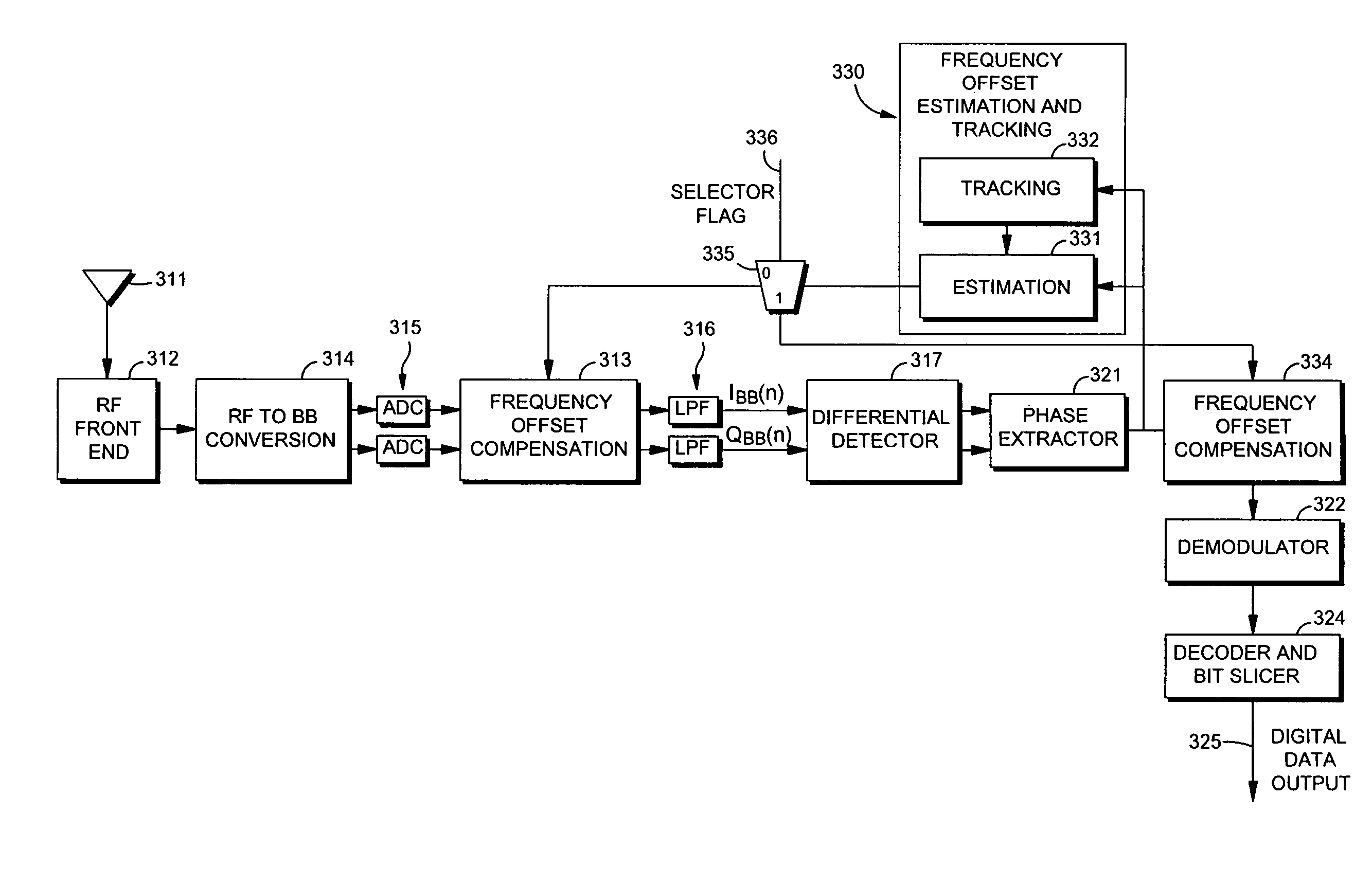
[0051]the invention is shown in FIG. 7 in which there is a programmable selection as to whether frequency offset compensation is performed in the phase domain or in the time domain. Like-numbered reference numerals are used in FIG. 7 relative to FIGS. 3 and 6, for similarly-functioning blocks.
[0052]In FIG. 7, programmable selector 335 provides the estimate of frequency offset either to a time domain-based compensator 313 or to a phase domain-based compensator 334. Selection of the destination is programmable in accordance with selector flag 336.
[0053]FIG. 8 is a generalized flow diagram showing methods performed by the invention herein. The process steps shown in FIG. 8 may be carried out by a hardware apparatus embodying the invention, or they may be carried out by software embodying the invention, or in hybrid hardware / software systems. In the case of software, the software is ordinarily stored on computer-readable memory media such as ROM or EEPROM which stores computer-executabl...
PUM
 Abstract
Description
Claims
Application Information
 - R&D
- Intellectual Property
- Life Sciences
- Materials
- Tech Scout
- Unparalleled Data Quality
- Higher Quality Content
- 60% Fewer Hallucinations
Browse by: Latest US Patents, China's latest patents, Technical Efficacy Thesaurus, Application Domain, Technology Topic, Popular Technical Reports.
© 2025 PatSnap. All rights reserved.Legal|Privacy policy|Modern Slavery Act Transparency Statement|Sitemap|About US| Contact US: help@patsnap.com


